
The fuel injection systems measures and manages engine operation. The major function of fuel injection system is fuel injection in ideal relation of air and fuel no matter what condition and operation range on which engine is. This relation is called stoichiometric relation.
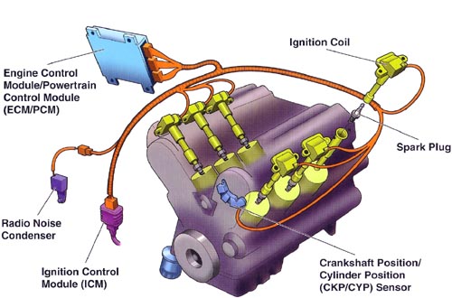
The system data are information about engine condition and range on which it is operating. Those are detected by sensors, these are installed on strategic positions around the engine, and then sent to PCM, the Power Control Module.
The PCM does receive data from sensors and compare it with programmed data in your memory. From this comparison, it does control the actuators properly.
This article focused to present an explanation about the features and operating of the fuel injection system.
Components
- Sensors;
- Electronic Control Unit;
- Actuator.
Sensors
Sensors are component housed in important points of the engine, such as camshaft and crankshaft gear, engine head and exhaust pipe. Your function are send information to PCM about engine operation. An engine has various types of sensors, they are:
- Resistive;
- Hall signal;
- Inductive;
- Capacitive;
- Switch.
Power control module

Actually, the PCM is ordinary CPU, but in this case it receives data from sensors, processes (compares with data already programmed) and controls the actuators for extract the best performance of the engine. In the beggining of the fuel injection system this are called ECU or electronic control unit, because eighties and nineties cars do not have many electronic modules, thus PCM are called ECU. Today this designate an ordinary module that could an ECU from ABS or onboard ECU.
Actuators

Actuators are components responsible to keep the engine operating according to the PCM commands.
Sensors
Sensors are small electronic components that monitor engine behavior during operation, and housed in various parts of the engine, from intake to exhaust. Sensor converts any physic or chemical phenomena in electric signals, these are data used by PCM analyse how engine is operating and compare data of sensors with data of injection map programmed in ECU.
Types of sensors
Resistive sensors
This kind of sensors are based in resistors, your input electric signals from PCM are 5 volts, and output electric range varies from 0 to 5 Volts according to resistor variation.
Capacitive sensors
They are based on capacitors, in other words, they can accumulate electric charges. Also send to PCM electric signals that varies between 0 and 5 Volts.
Inductive sensors
This type of sensor do not need any referential tension from PCM, it can generate tension by yourself. Inductive sensors are common in crankshaft gear, to communicate PCM which is engine speed. Generally, it is composed by a magnet and a sensor, this are exposed by electromagnetic field produced by magnet, and this generate an electric tension on sensor.
Hall effect sensors: Hall sensors operate are similar with inductive sensors, the difference is the type of the electric signal. In hall effect sensor the electric signal are pulsed, the continuous 12 V tension from PCM are converted in pulsed signal (square wave signal). This type of sensor are commonly used in ignition distributors.
Switches
Theoretically, this are not a sensor because only 0 or 5 V are sent to ECU, switches are used where only two states occurs, for example, oil pressure switch. In this case, the PCM will only receive a signal from switch about two states of lubricating system, pressurized or not pressurized.
Classification
The fuel injection operation of nowadays systems differ a bit from older system, the type of PCM, amount of injectors, ignition and injection mode are characteristics that defines performance of fuel injection system. The older systems was intermittent or bank to bank, has dynamic ignition, and do not provide a good atomization between fuel and air, but still better than carburetors. Those characteristics will be present above:
- Type of electronic control unit: Analogical/Digital
- Number o injection valves: Mono point/Multi point;
- Mode of injection: Intermittent / Bank to Bank / Sequential;
- Admitted air mass calculus: TBI Angle /Engine Speed, Speed density / Flow rate or Air Flow / Air mass direct read;
- Air / Fuel mixture control: Open loop / Closed loop;
- Ignition type: Dynamic / Static.
Type of electronic control unit
The first ECUs are analogical and bigger than new ones. The fuel injection system was two ECUs operating on engine. First, ignition system control ECU. Second, fuel injection ECU. These two are interconnected, because the moment of ignition depends on what information about the engine the ECU has.
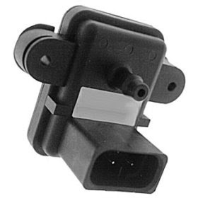
The new ECU do not have the ignition module, this are incorporated on fuel injection ECU. Some ECUs also have a little duct that works with a atmospheric pressure sensor, but it is a system that was substituted by a tiny MAP (Manifold Absolute Pressure) sensor.
Number of injection valves
For years the amount o injection valves has an option of one and various injectors. A fuel injection system with one injector are called mono point and a fuel injection system with various injectors are multi point. While more injectors result in more cost, the mono point also has some similar weakness with carburetors. This system has one injection housed in the TBI (Throttle Body Injection). The objective is pulverize the fuel on air mass flow that pass through the throttle which is piped to all cylinders. This configuration requires a great amount of fuel to atomization in a great amount of air, and due to the longer track to the cylinder, a considerable part of fuel does condense on air intake manifold walls. For this reason, mono point fuel injection system are discontinued.
The multi point fuel injection systems not only have more injectors, as well this are housed very closed to intake valves. Each cylinder has one injector, and it does operate just in time defined by the PCM. The advantages are freedom to design the intake manifold, this do not have fuel circulating inside it, then it can have the internal space larger than systems with mono point injection and materials like polymers can be used instead of aluminum, that are lighter and cheaper than it and also have smoother internal walls. This last feature contributes to reduce resistance against air flow inside the intake manifold.
Mode of injection

Intermittent
This mode are characterized by activation of all injectors even only one cylinder are in admission stroke. This means that only one air/fuel mixture are admitted and the other are on stand-by next to intake valve until respective cylinder stars admission stroke too.
When a cylinder, previously, in any stroke except admission, starts your admission stroke, the air/fuel mixture already injected are supplemented by more one fuel injection. This represents more fuel spent by the engine and more emissions produced due to air/fuel rich mixture.
The injectors are activated each crankshaft 360° rotation, but in during operating on temperatures above the operate temperature (cold phase), those are activated 180° rotation of the crankshaft.
Bank to bank
Similar with intermittent injection mode, bank to bank injection mode does operate activating a group of injectors respective to cousin cylinders. For example: On 4 cylinder engine the order of ignition 1-4-3-2. The cylinder pair 1-3 and 4-2 are cousins. Therefore, only a group of injector will be activated, the number of those depends on how many cylinders the engine has. Bank to bank injection mode does activate the injector each 180° of rotation of crankshaft, and amount of fuel injected are reduced as the heat reach ideal temperature. This mode was widely used in replace to intermittent, but was discontinued by sequential mode.
Sequential
The sequential injection mode is the most accurate of them all, it does reduce at maximum the loss by condensation in intake manifold walls. However, to support this method, the PCM needs a major level of data to operate the injectors properly. Each injector are individually activated to inject fuel just in the moment when engine needs. This mode of injection are presently in use.
Admitted air mass calculus method
TBI Angle / Engine Speed
The TBI angle (position of throttle valve inside TBI) and engine speed data are most important data on this method. These are used by PCM to calculate the amount of fuel needed to completely burn the air mass admitted, the sensors used for this are engine speed sensor (inductive or hall effect) and TPS (throttle position sensor), but this case a more accurate sensor are needed. With those data, the PCM converts the TPS data in percentage and compare, TPS data and engine speed data with data contained in EPROM of the PCM.
Engine speed / Air density
Similar TBI Angle and Engine Speed mode, Engine Speed and Air Density mode (also called Speed Density) also is a indirect method of air mass calculation. This means that the fuel injection system need more than one sensor to obtain the amount of air mass admitted by the engine. For speed density mode, the fuel injection system needs two main data from the engine, one is the manifold absolute pressure and the other is the engine speed. With engine speed data the mass air flow data are obtained, that is measured by engine speed sensor. To measure the pressure inside intake manifold, a MAP (Manifold Absolute Pressure) sensor are used. However, another data is needed to measure air mass density, the temperature. Thus any speed density has a temperature sensor, but in newer versions the MAP and temperature sensors are combined in one casing, this is called combined sensor. Therefore, with engine speed, the PCM can measure the cylinder charge, with combined sensor (or map sensor and air temperature sensor) the PCM can measure the air mass density. With density and air mass flow rate, the air mass admitted can be calculated.
Air flow
The first direct method of air mass calculation. This does operate with air flow sensor combined with temperature and atmospheric pressure sensor. Based on these sensors, the PCM has data about air flow, air temperature and ambient environment pressure, and with these it can measure directly the air mass admitted. The variation on environment condition, like pressure and temperature, are detected by temperature sensor and atmospheric pressure sensor, then the PCM does adjust the injection time with that new condition.
Air mass
This also is a direct method of air mass calculation, but in this case, the air mass value is direct measured by the Mass Air Flow Sensor (MAF Sensor). This does operate based in a hot wire principle. In sensor casing, the part of it that are inside intake manifold has a wire. This are submitted an electric current that heat the wire. When engine starts, an air flow start to flow inside intake manifold, so the air flow through the hot wire. The air does change heat with heated wire, it loss heat by the air. To keep wire heated, more electric current is needed, and then PCM can measure how much air mass are admitted by the engine. Air mass calculation mode is the most accurate method and do not need any data about pressure or temperature, the MAF sensor data are admitted air mass.
Air/Fuel mixture control
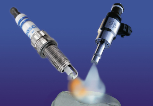
Any fuel injection system operates with data about engine conditions, but some data are information about what is entering and exiting from engine. The engine does admit air/fuel mixture and does expulse combustion gases. These are composed by CO, CO2, N2 and H2O, if a great amount of CO2 are going out of the engine, this means that air/fuel mixture has a great amount of fuel, more than necessary (rich mixture), and this excess are going out of the engine. This affect engine consumption and emission.
The fuel injection system are design to control the engine operating, keeping it inside gases emissions rules and with good fuel consumption. For a more accurate control, the fuel injection system can control the air/fuel mixture with open or closed loop. The main difference between these two are the lambda probe (O2 sensor or lambda sensor.). This measures the percentage of O2 in exhaust gases and give this information to PCM, then it adjust the injection time to inject only the fuel necessary to burn the amount admitted mass air.
Open loop
When the fuel injection system do not have the lambda sensor it is operated under open loop, in other word, without controls of exhaust gases. Therefore, the accuracy of injection system is reduced.
Closed loop
With a sensor lambda installed on exhaust pipe, the system operates under closed loop, the exhaust gases are monitored and analyzed by lambda sensor. This gives the percentage of O2 in exhaust gases, and send that to PCM.
Ignition type
Dynamic ignition
Even with carburetor discontinuation, this type of ignition still used on engines. Dynamic ignition is characterized by the use of distributor, a device coupled on engine that operates synchronized with it. Inside the distributor is a rotor mounted over a hall effect engine speed sensor, this rotor turns (For this called dynamic) synchronized with engine, then the sensor send to PCM the engine speed information. The rotor has a metallic plate that receives electric current from ignition coin and distributes it for spark plugs properly. However, this device was discontinued for constant wear of your components.
Static ignition
In this method the ignition are controlled by the PCM, a subsystem inside it are responsible to control the current to ignition coil, then to the spark plugs. Therefore, due to sensors the PCM determines the ideal moment to release the current from spark plugs. The electric current can be sent for one spark plug or a group of spark plugs respective to cousin cylinders. In this case, the current are sent to more than one spark plug. The intensity of electric current will be bigger in cylinder that are in combustion stroke than in cylinder under another stroke, because the environment on combustion chamber inside the cylinder requires more current to produce ignition, the other cylinders will have a weak current producing a weak spark.
Operation
The engine has the electric system that supplies all devices and the fuel injection system. Even when engine are off, the battery keep a little current on injection system, this current are called key off load. This are responsible to keep the PCM on stand-by without losing some information.
When we turn the key to the first stage, usually position 15 (or MAR), the fuel injection are totally energized by the 12 Volts automotive battery. On this moment the fuel pump is fed by battery and pressurizes fuel line. The pressure of fuel line is around 3 Bar, and in this moment, the injectors are closed and over 3 Bar pressure from the pump. Some seconds after this, the fuel injection cut the electric current for pump and only send it again when the signal from engine speed sensor are received, in other words, when engine starts to operate.
If we turn the key again, until position 31, we are sending electric current to engine starter, this start to operate and the engine begins to work. In this moment, the engine sensor detects rotation from crankshaft gear (or phonic wheel) and sends this information to PCM. This activate the fuel injectors and, again, the fuel pump. The fuel are properly pulverized (injected) and mixes with admitted air. When the intake valve opens, the air/fuel mixture get in the cylinder. After the piston finished the admission stroke, it starts compression stroke, compressing air/fuel mixture until reach the TDC (top dead center). Therefore the PCM release the electric current to ignition coil and this to spark plug, a spark is produced and the combustion begins. Finally, the engine start to work itself and the starter are deactivated.
After start, the engine do not reach the ideal temperature, that is over 95°C. To reach it as fast as possible, the PCM injects more fuel than in normal condition. This is called cold phase operating, and it monitored by temperature sensor. When it detect that the engine reached the operating temperature, the PCM receive this information and proceeds reduction of injection time progressively.
Another component that depends from a determined temperature is sensor lambda, this sensor only works properly after reaches 300 C, until there your signal is ignored by the PCM. However, some lambda sensors have a heater to help it to reach the operate temperature as fast as possible. With lambda sensor signal, the PCM does adjust the time of injection.
With the engine operating at normal operating temperature, the PCM always activate the injectors just before the moment that piston starts the intake stroke. The engine speed and phase sensor are important to this occur properly. The engine speed sensor indicate engine speed and which cylinder are on TDC, the phase sensor indicate the stroke occurring on each cylinder. Therefore, the PCM combine these two data and determines when each injector must be activated and how long they still activated.
During operation, the fuel supply system is kept activated by the PCM, then fuel line is always with 3 Bar. But the excess of fuel sent to injectors returns to fuel tank. Because of the contact with engine heat, this returns hotter than when it was on tank. This increase the fuel temperature in tank, a part of the fuel vaporizes, and fuel vapor are piped by recirculating system. The fuel vapor are ducted to activated charcoal filter. A purge valve sends the fuel vapor to intake manifold. The purge valve operation is controlled by the PCM, that knowing data like engine temperature and percentage of O2 in exhaust, activate the purge valve appropriate the fuel vapor and reduce the emission level.
The PCM also recirculate the combustion gases, data about engine temperature, speed and percentage of O2 help it to determine when it does recirculate combustion gases. A valve that are responsible for combustion gases recirculation, is the EGR valve (Engine Gases Recirculation). When activated, it diverts some part of combustion gases back to the intake manifold. This recirculation helps the engine to keep inside of emission rules.
References
- BOSCH, Robert, Manual de Tecnologia Automotiva. 25.ed. Edgard Blücher LTDA, 2004. 1231p;
