
The purpose of supplying pressurized fuel to engine fuel spray devices (carburettor or nozzles) is delegated to the supply system. With the increasing evolution of motors and electronics, important changes in system operation were made. The carburetor and mechanical pump have left the scene to make way for the actuators, sensors and electronic control unit (ECU).
These are gradually being replaced by a variation of their previously indirect injection system, with fuel being sprayed at the end of the intake manifold, to direct injection systems, with fuel being sprayed into the combustion chamber. Thus, the feeding system has three variations:
- Carburetor feeding system;
- Electronic injection feeding system;
- Electronic direct injection feed system.
This article aims to detail the components of the carburetor feed system.
Carburetor feed system

The carburettor system is already out of favor for the automotive market, yet the number of carburettor vehicles still on the road is large, and this makes this obsolete system no less important in terms of learning. In this the fuel is propelled to the carburetor through a mechanical pump driven by an engine shaft, or cranks, or the valve control. The components of the carburetor feed system are:
- Fuel tank;
- Feed pipe;
- Fuel filter;
- Fuel pump;
- Carburetor;
- Air filter.
Fuel tank

It is the component responsible for storing fuel in the vehicle, is in direct contact with it, and therefore needs to be made of materials that resist the chemical attack of the fuel. It is largely made of steel and internally coated with layers of tin, lead or chrome for corrosion protection. Later this material had to be replaced to resist the use of ethanol.
The capacity of a tank as well as its position in the vehicle are factors to be determined in its design. The tank can be positioned at the front, center or rear of the vehicle.
For filling to be possible, the tank has a nozzle that connects to a hose, which is closed by a cap located on the vehicle body. Next to this nozzle is another nozzle that keeps the tank under atmospheric pressure, making it easier for the fuel to exit the engine. This nozzle also served as a vent for fuel vapor polluting the atmospheric air, but after 1990 was included the canister system that filtered the vapors and sent them to the intake manifold to be burned. by the engine.
Fuel tank components
- Fuel Volume Gauge: This is a potentiometer in which the rod in contact with the resistive curve is the same rod that is attached to a float. This float is directly in contact with the fuel and its displacement changes the potentiometer’s final voltage, ie the fuel measurement on the panel;
- Filling nozzle: It is nozzle where the fuel is filled in the tank;
- Outlet tube: Tube that drives the fuel to the pump;
- Internal Partitions: These are plates made of the same material as the tank to avoid shaking the fuel inside the tank when the vehicle is moving. These plates allow fuel to be kept at the same level at various points in the tank, and avoid inconvenience such as noise and sudden changes in fuel level indicated on the panel.
Feed pipe
Piping that carries the fuel sucked into the pump from the tank to the carburetor tank. Piping fabrication material varies with the type of fuel used, and also has treatment on the inner surfaces to resist the chemical impact of the fuel. The most common materials are polymers, steel or copper. At its ends there are quick coupling devices or clamps.
Fuel filter

Its purpose is to retain impurities contained in fuels, both coarse and finer particles, as the carburetor has several calibrated holes of millimeter dimensions that would be easily affected if debris reached them. If the filter is used for a period beyond its maintenance specifications, it may become particulate and reduce the flow of fuel to the carburetor, and therefore the engine power. In carburetor feeding systems there are three types of fuel filters already employed:
- In-tank fuel filter;
- Filter installed on the pump;
- In-line fuel filter.
The most common materials in the fabrication of filter elements are metals, ceramics and paper. Filter elements are pore screens through which fuel will flow. These screens can be made with a combination of the materials mentioned above, and are designed specifically for a particular feeding system. It is the feeding system that indicates the filtering power of the filters.

From the latest carburettor fueling systems to today’s electronic injection systems, the most commonly used fuel filter is the fuel line filter. In factory standard cars they are armored, but there are detachable models in the aftermarket.
For this type of filter, follow the recommendation in the mounting position, usually indicated by an arrow. If the filter is incorrectly mounted, its life will be severely shortened. In demountable filters the filter element can be easily removed and washed without changing.
Fuel pump

With the fuel tank away from the engine, a pump must do the job of pushing fuel into the carburetor. Carbureted engines used two types of pumps, mechanical and electric.
The mechanical pump is a motor driven device that is mounted on the engine to be driven by the camshaft or crankshaft. Because of this the pump is exposed to the high temperatures that the engine reaches. Its operating speed is directly linked to the engine operating speed. The basic components of a mechanical carbureted engine pump are:
- Cover: Provide upper pump seal, is tight over gaskets to prevent fuel leakage;
- Upper Body: It is part of the pump where the inlet and outlet valves are located;
- Diaphragm: Made of fuel-resistant rubber, its function is to cause fuel depression and compression within the pump;
- Spring: Located inside the lower body, it works by pressing the diaphragm upwards to compress the fuel inside the pump and opening the outlet valve;
- Lower Body: Session of the part that is bolted to the motor, and also supports the entire pump;
- Rocker: Receives directly the action of the shaft that drives it, is connected to the diaphragm stem and performs its downward movement.
Air filter
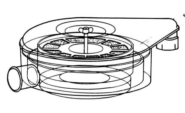
As the engine aspirates atmospheric air to prepare its air / fuel mixture, it is exposed to other impurities contained in the air. Industrial emission gases, mineral particles, soot produced by diesel engines, pollen and dust are contaminants which, if aspirated without any filtering, reduce engine life through lubricating oil contamination.

In carbureted engines the air filter was mounted on the carburetor, usually circular in shape and made of resin-treated fibrous paper arranged in accordion form. Vehicles with oil-plated air filters were also common, in which case the fibrous paper protected by a wire mesh was moistened with oil. The oil retained in it the impurities of the suction air, and the filter promised unlimited life, provided that it was properly maintained, cleansing to remove the oil impregnated with a new oil.
References
- SENAI, Série Metódica Ocupacional;
- CHOLLET, H. M., Curso Prático e Profissional para Mecânicos de Automóveis: O motor e seus acessórios, Lausanne, Hemus, 1996. 402.
