When analysing a vehicle dynamics it easy to find itself looking for a reference for the coordinate system. It is enough just one wrong reference to get confused when a moment or a force is exhibited with a negative signal. Hence this post will aprouch the most adopted coordinate reference of vehicle tires in the field of dynamics, the cartesian tire coordenate system (CTCS) and SAE tire coordenate system (SAE TCS).
The cartesian tire coordenate system (CTCS)

The first step to understand the tire-road interaction and force system is plot a cartesian coordinate frame at the center of the tireprint. In this case, it is always assumed a flat and horizontal ground condition. The reason is since the texture of the road surface is not relevant for the definition of the rim kinematics
the results are quite reasonable. Another assumption is that the rim is a rigid body. According Guiggiani [2] a wheel has six degrees of freedom. However, due to the first assumption, only two degrees of freedom are realy relevant.
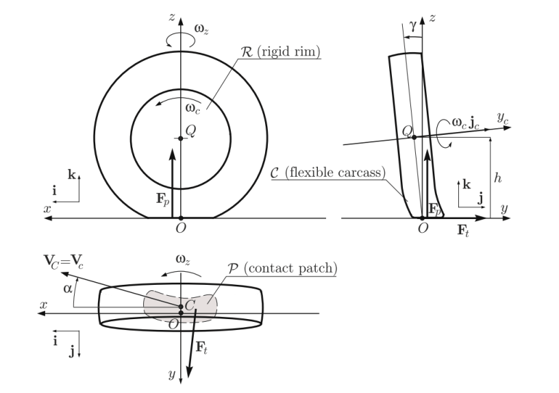
The x-axis is established projecting a line along the intersection line of the tire-plane and the ground. The tire plane can be understood imagining a cut of the crossectional are of the tire, hence it is a plane with a shape of a flat disk. The z-axis is perpendicular to the ground, in the way of the gravitational acceleration g, but in the opposite direction. Finally, the y-axis, and this is important, because it defines the coordinate system a right-hand triad.
The second step is the tire orientation. From the cartesian coordinate of a tire, two angles have great importance in tire dynamics: camber angle γ and slip angle α, also known as sideslip angle [1]. The camber angle is the angle between the tire-plane and the vertical plane measured about the x-axis [1,2]. The slip angle α, is the angle between the velocity vector v and the x-axis measured about the z-axis [1,2]. Another assumption of great importance is that a tire suffers forces from the ground at the center of the tireprint, then these can be decomposed along x, y, and z axes.
Main parameters
The forces and moments in this cartesian system are listed below:
- The longitudinal force (Fx) is a force acting along the x-axis. When is Fx > 0, it means that the wheel is accelerating. Conversely, Fx < 0 if the wheel is being braked. Longitudinal force is also called forward force [1].
- The normal force (Fz) is a vertical force, normal to the ground. Important, the reference is positive (Fz > 0) it is upward. Normal force is also called vertical force or wheel load [1].
- The lateral force (Fy) is a force, tangent to the ground and orthogonal to both Fx and Fz [1]. This is the force that initiate the slip angle. The resultant lateral force Fy > 0 if it is in the y-direction.
- The roll moment (Mx) is a moment around the x-axis. When admit positive values (Mx > 0), it means that the wheel tends to turn around the x-axis. This movement is also known as bank moment, tilting torque, resistance torque or overturning moment.
- The Pitch moment (My) is a lateral moment about the y-axis. When resultant pitch moment My > 0 the wheel tends to turn the around the y-axis. In other words, this is the forward movement of the wheel. The pitch moment is also called rolling resistance torque.
- The yaw moment (Mz) is an upward moment around the z-axis. A positive yaw moment (Mz > 0) tends to turn the tire around the z-axis for right side. The yaw moment is also called the aligning moment, self aligning moment, or bore torque.
The origin of tire coordinate frame (O) is sometimes the source of problems in the moment of tire modeling. Understanding that all vehicle wheels are cambered, it is difficult to identify or admit a center
point for the tireprint to be used as the origin of the tire coordinate frame. Hence, it is convenient to assume that O is at the center of the intersection between the tire-plane and the ground [1]. According to Jazar [1], this means tht the origin of the tire coordinate frame is at the center of the tireprint when the tire is standing upright and stationary on a flat road.
SAE tire coordenate system (SAE TCS)

The SAE tire coordinate system adopted by the Society of Automotive Engineers (SAE). This sistem is similar to the system describerd before. In this case the center of the tireprint is the center of the SAE TCS when the tire is stationary. Although the x-axis is at the intersection of the tire-plane and the ground plane, which is similar to CTCS, the z-axis is downward and perpendicular to the tireprint. The y-axis is also different. Is in the ground plane and points to the right, hence SAE TCS is a righthand frame. In addition there are difference in the angles. For instance, the sideslip angle (α) is positive when the tire is slipping to the right. The camber angle (γ) is positive when the tire slopes to the right. The SAE coordinate system is as good as the coordinate system. Although can be confusing the different orientations of z and y axes, this system commonly used in the field of motorsports and academic research.
Reference
- N. JAZAR, Reza, Vehicle Dynamics: Theory and Application, New York, Springer, 2008. 1015p;
- Guiggiani, Massimo. The Science of Vehicle Dynamics. Handling, Braking, and Ride of Road and Race Cars. New York, Springer, 2014.
