
The four wheel drive vehicles are important by several reasons, for instance, to overcome off-road paths, to provide a good stability and to make possible the torque vectoring. However the drivetrain it is quite complex relative to a single wheel drive drivetrain. The main objective is to provide the correct velocity of the wheels when under cornering, because not only the wheels of the same axle must have different speeds but also the different axles must have different speeds inside a corner . Hence this article aims to explain and summarize the main mechanisms proposed to be used in 4 wheel drive transmissions, the split gear box and the viscous coupling, but also explaining the balance of the driving torque.
Basic structure
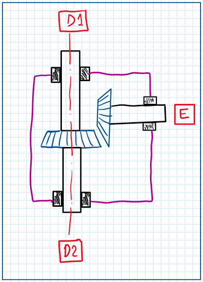
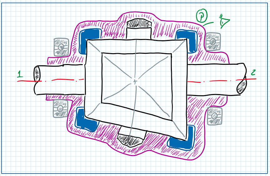
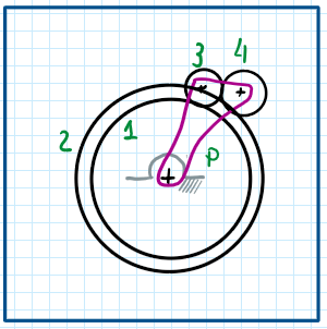
The main four wheel drive transmission requirement is that the drivetrain efficiency must be equal for both axles. In general this system can be represented by a rigid connection as seen on the Figure bellow. The connection between the axles can be done rigidly but in this case this does not obey the pure rolling conditions, except for off road traveling. In this situation the wheel slip is assumed. Therefore a rigid transfer must have more than one degree of freedom . The inclusion of a proper transfer case or center differential transform a 1 degree of freedom connection to a 3 degree of freedom device whose are the rotations of the axles from the front, rear and engine.
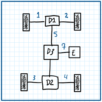
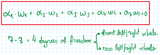
Therefore the architecture of a four wheel driveline is composed by 7 shafts and 3 differentials. Hence fixing each wheel rotation axles 1, 2, 3 and 4 it is possible to find the rotation of the engine as a function of these four. This is possible, because when the system is engaged the differentials reduces the degree of freedom of the axles from three to two, which is rotation of each wheel. If the system are all disengaged, thus 7 degrees of freedom are able. In both conditions the pure rolling condition are respected thus it is possible to write the following equation :
The virtual works theory
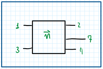
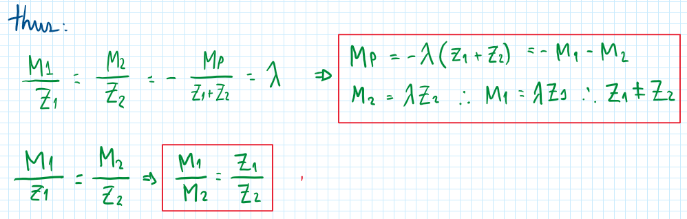
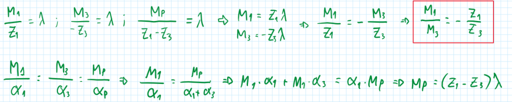
Applying the theory of the virtualworks, the drivetrain is considered a big gearbox.. Actually it is considered a black box which comprises the first, the second differential and the center differential in one component. Hence it is possible to develop the following equations :

On the equations above, Lambda is a multiplication factor. With all these relations it is possible to assume that the moment on axles one and two are the same. Hence, the factors A1 and A2 are also equal so we can call them A12. This is a mathematical approach which obeys the pure rolling conditions. Thus:
At the end, all parameters can be correlated to the engine rotation and then it is possible to find a function of it relative to wheels rotations:

Optimal balance of the driving torque

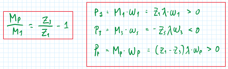
This is a critical point in the development of a four wheel drive drivetrain, because for the transmission device be able to split the torque, it must have an efficiency perfect at least at straight line travel. Hence considering central drivetrain the following equations and correlations can be developed. Assuming that the efficiency must be one, then R1 equals R2, because they have the same wheel size and Tau 1 equals Tau 2. with these assumptions, the system is able to provide F1 equals F2 and an efficiency equals to one. However understanding that even at low general direction there are considerable load transfer the F1 cannot be fixed equal F2, thus F1 is different that F2. Therefore differentials are not suitable for transmission of torque between axles. One of the solutions is the application of bevel gear split torque transmission.
The bevel gear split torque
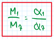
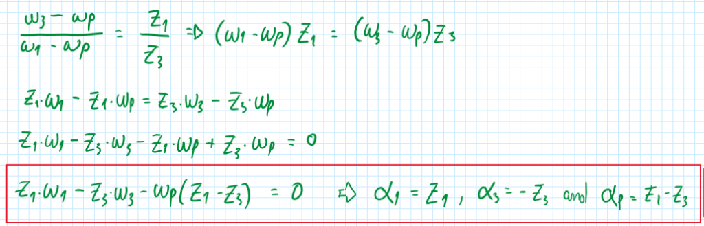
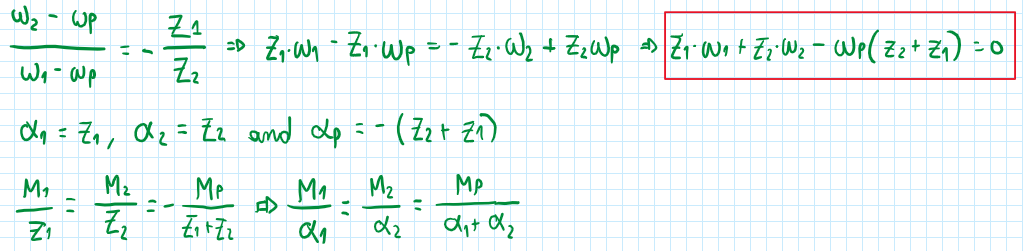
As can be seen the split torque equation means that Z1 is different from Z2 and this is a compulsory relation, because if equal it will operate as a differential. Therefore, it requires a different output speed, thus it can be written the following relations :

The split torque geartrain with cylindrical wheels

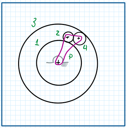
This is almost the same as the previous device, but with a higher efficiency during straight line traveling. As a characteristic of this transmission device, there are two output shafts, but it must be determined which of them are connected to the wheels. In this way the following equations must be developed :


There are two shafts rotating at the same orientation and one at the opposite one . Thus the carrier shaft, which is given by P, is the input and this defines that the 1 and the 2 shafts are the outputs.
The split torque transfer case with cyllindrical gears
In this variation of this split torque transfer case, a different number of gears are used. In general two cylindrical gears are used. A total of four wheels are applied by the system, one of them is used to reverse the rotation direction of the ring gear. Hence the following equations can be developed :
As can be verified, the two output shafts are the 1 and the carrier, the shaft 3 is the driving shaft, which receives the power from the engine.
There is another variation of this type of split torque device, in this one the ring gear connects with the 2nd planet gear externally. For this case the application of the virtual works principle retrieves the following equations :

Therefore, during the driving phase, the carrier P is the input and propels the car, but during acceleration, P is now the resisting member.
The viscous coupling

The use of a viscous coupling to transmit torque for both axles is another type of transmission but without torque split. In fact this system operates by demand. The power out of gearbox goes to the front and rear axle. Depending on the configuration, a viscous coupling is needed between those, in general before the rear axle. The result is that the torque transmission only occur after some delta between front and here excel velocities. The viscous stress on the fluid is given by the equation:
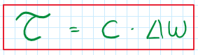
Where C is the efficiency and delta W, the difference between angular speed of these axles. In addition, if during braking the front wheel became locked, the torque transmitted will be inverted and the rear wheel be prone to lock, which is an extremely critical condition. One of the devices added to avoid this is a free wheel, which permits that an axle can receive torque in only one way.
References
- Guiggiani, Massimo. The Science of Vehicle Dynamics. Handling, Braking, and Ride of Road and Race Cars. New York, Springer, 2014.
