The straight forward movement in automobiles are stricktly connected with its performance. In the previous article, the basics of longitudinal dynamics were analyzed for rear wheel drive vehicles. These are the most traditional automotive powertrain arrange. However, not only this was not the most used as there another important factors to be defined. This article will approach the basics of four wheel drive dynamics and the definition of gear ratios for daily situation of a car.
Four wheel drive vehicle dynamics
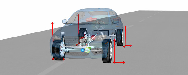
In the previous article a longitudinal dynamics analysis was done in a rear wheel drive vehicle, at low and constant speed. now considering a four wheel drive vehicle at the same conditions, it is required to establish the following assumptions:

The last assumption suggests that both axles develop the same amount of grip. Hence the maximum friction coefficient (Mumax) corresponds to the maximum traction developed buy these tires and about this it can be written:
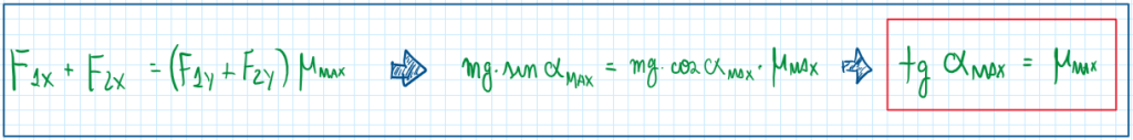
Therefore, if the maximum friction coefficient equals to 1, then the maximum slope becomes 45 degrees. However this condition is only obtained for four wheel drive vehicles in optimal conditions. Any case except this will exhibit any smaller maximum slope angle, even in rear or front wheel drive vehicles. Considering a situation of maximum speed in a four wheel drive vehicle, the assumptions are:

As can be observed, considering that the engine has sufficient horsepower to propel the vehicle to its maximum speed, this one will be obtained according to the equation above. Hence the maximum speed depends on the vehicle mass, the friction coefficient and the aerodynamic parameters. In fact, these are the most important parameters, mainly Cz. This one is the lifting coefficient, generally is given by positive values. In cases which lifting increases too much, the value of the quotient tends to 0, thus the velocity tends to Infinity. The opposite case occurs when Cz is negative, which means downforce. This is the case of sport vehicles. When the downforce is too high, the value of Cz become too negative that the velocity resultant is a complex number.
Power required for traveling at constant speed
Once this conditions were investigated for different kinds of powertrains, it is possible to define the power acquired for traveling at constant speed. This is one of the main situations which automobiles must face. As in the previous situations this one is defined by specific assumptions:
- zero acceleration;
- no slope;
- aerodynamic effects.
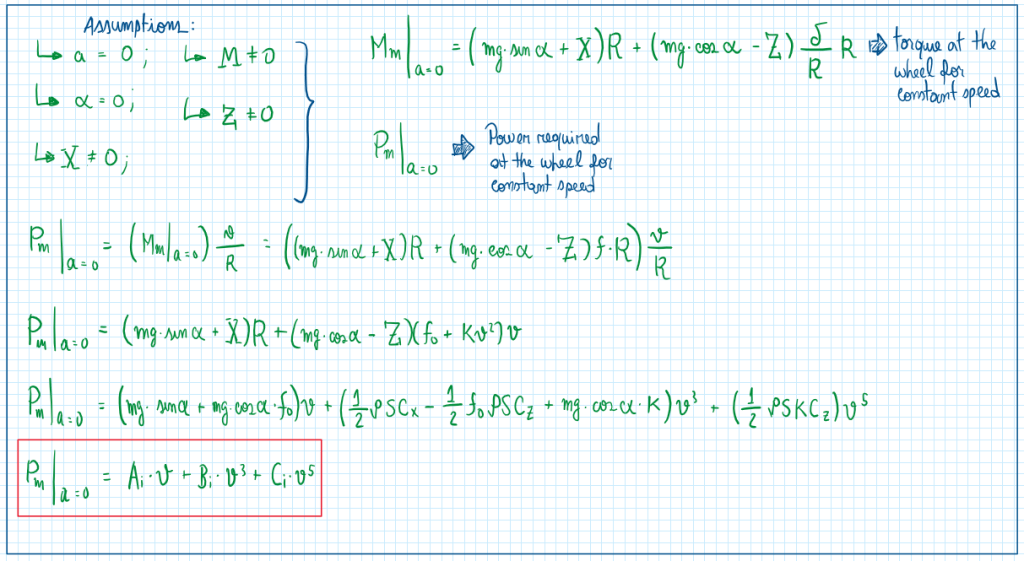
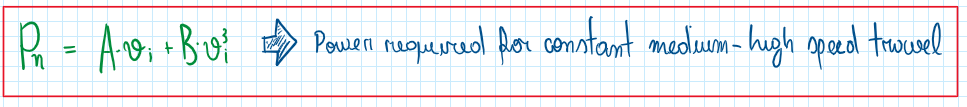
By observing this equation, a vehicle is able to travel at constant speed if it overcomes all the loads due to weight and rolling resistance. This one increases with speed but owing to their low values, only become significant for a constant speed cases. For high velocities it is usually neglected. The parameter K is not so significant in terms of absolute values, but being part of CiV5 make them a considerable variable for very high speed traveling conditions. Therefore the equation for power required by constant speed traveling is given by:
Introducing the characteristic power curve
These calculations are performed to define the requested power and the torque at the wheel to overcome all the loads. However this power and torque does not means the engine output. Instead, the power at the wheel is a load which must be fitted into engine performance, in other words, in the power-speed graph. Considering that the powertrain has the following structure:

To adequate the powertrain to the vehicle loads, the transmission relations must be selected, mainly TauM from the gearbox. In fact TauM adopts one value for each gear, thus the evaluation of the powertrain against vehicle loads must consider all gears. The next step is the coupling between the engine power (Peng) and the loads (Pn) to identify the optimal gear ratio for the maximum velocity of constant speed condition already identified before. Thus considering the following relations:

Now, the graph between power and speed can be updated:
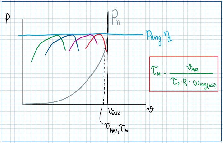
As can be observed, changing TauM it is possible to obtain several power curves, each of them touches the line of constant engine power. However, the curve respective to the power load is a parabolic one, because the rolling resistance and the aero loads increases with the cubic of the velocity. The point which those curves touch is the one which the power curve within a specific TauM must reach . Therefore for that maximum speed, it is required and specific gear ratio, which can be determined by the following equation.
Selecting the proper gear ratio for a specific Vmax
The selection of the proper ratio takes into account the fact that in some cases the gear size must not be the desired one, because of designing and packaging limitations. Thus considering the following arrange:
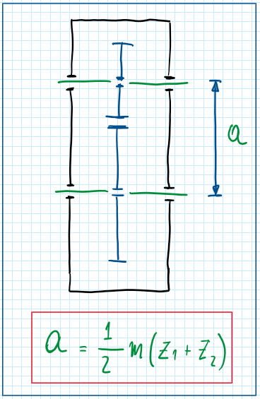
The perimeter “a” is the distance between two gears, it is usually applied to gearboxes due to the design limitations of the gears. This is a consequence of the minimum size that a gear must have, specially its teeth. Therefore the parameter has a minimum value. For instance considering a desired relation of Tau M equals to:
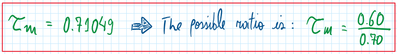
From this point a method used to define the ideal a value for any specific gear ratio is called the continuously fraction method.
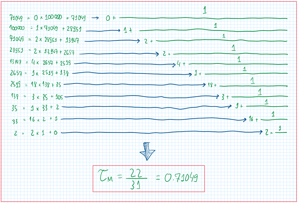
The first five approximations may be a good starting point to define a gear ratio which fits with the size limitations of the gearbox. In the end of this calculation a new “a” is obtained. However this one has a feasible values for both gears teeth. Instead of the previous one, this is a value which those gears can be designed inside the limits due to the size of the teeth.
Defining the lowest gear ratio
In general during the powertrain development, the definition of the lowest gear ratio taking to account the maximum slope which the vehicle is able to transpose. In this situation the vehicle needs the maximum traction capacity and for this a suitable gear ratio is required for it.

This first equation only deals with a condition which is already at constant speed. Thus this is not the lowest gear ratio requirement. Hence, considering a vehicle at maximum slope possible for its tires and starting from inertia:

Understanding that the engine delivers a known maximum torque at maximum rotation, and that there is no slip on the clutch, the output shaft will develop the maximum engine torque. As in the case of the gear ratio at constant speed, the objective is to correlate the two torques, the required torque and the engine one.

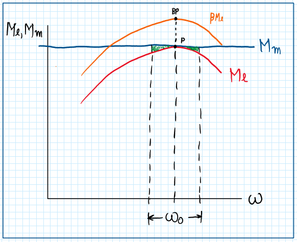
As can be seen on the graph the equation defined has a security factor beta. The reason for this is the rotation oscillations during engine operation. For that some assumptions are made, which means that there are some impulses on torque which results on oscillations of dw that increases on time. This represents oscillations about point P. However, if dw tends to zero, the oscillations are being reduced and w0 admits stable values. These oscillation region are inside the parabolic region.

Observing the equations above, the left side one exhibits the difference between Me and Mm respective to the graph. However if it is considered that all the loads on the vehicle are reduced into just one wheel, it is correct to define that the difference between torques is the inertia moment times the acceleration. Therefore considering those equations equal it is possible to develop the following calculations:

The oscillations on the angular speed depends on the time period delta T, the reduced inertia J, the coefficient Mu ( Mu bigger than 0 ). When delta T tends to infinite, dw1 tends to zero and the angular speed oscillation goes to 0, which means a stable system. However when dw1 tends to negative values, dw decreases and, if delta T is big enough, this system tends to an unstable condition which can result on the completely engine stall, consequently the vehicle stop . For this reason it is introduced a safety factor beta which displaces this the torque curves. Therefore, to avoid oscillation effects beta displaces the curve to values which are higher than the required. In general beta is around 0.8 to 1.0.
References
- Guiggiani, Massimo. The Science of Vehicle Dynamics. Handling, Braking, and Ride of Road and Race Cars. New York, Springer, 2014;
- GILLESPIE, Thomas D, Fundamentals of Vehicle Dynamics, Warrendale, Society of Automotive Engineers, 1992. 470p.
