There are some important features in the monocoque manufacturing process. As this this is the main component of a race car chassi, the stiffness of this structure defines if the car is able or not to hold very high wheel loads. A carbon fiber structure stiffness depends of how much this has interruptions in the carbon plies. For instance, holes, cross-section areas and inserts. This last one is very important since its main functions is to provide a rigid support for possible attachment points. In these suspensions, engine, wings and body work are fixed. This article propose a review over the main strategies to build inserts inside carbon monocoques of open wheels race cars.
Overview
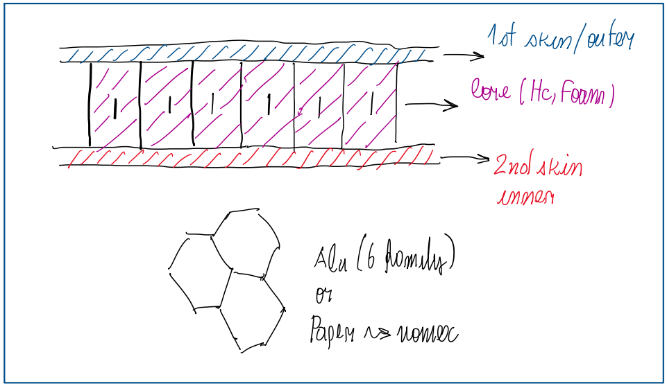
Basically the monocoque have inserts in sandwich structures, which are made from different materials. An example can be seen in Figure 1. There are layers of carbon fiber and between them a core, which can be honeycomb or foam. The first one is made from aluminum 6xxx series or Nomex, made from DuPont. Foams usually are made Rohacell and polyurethane. The main reason to use cores is to increase the cross-section, thus reduce the bending stress. In addition, since cores a lightweight, the weight of the monocoque is no penalized. However, inserts are added to the chassis to provide means to connect components to the chassis, mainly through fasteners. The other function of the inserts is to be a local support, a hard point against the loads from the components which are fixed on it. Since the bending stiffness of the carbon fiber alone is low, thus the core is applied between the layers. However, the honeycomb (HC) has a very low stiffness, mainly in the plane through bending occurs, it is required something to improve the local stiffness. This is a hard point, an insert. An example of insert is the which supports a suspension bracket. A thread must be cut in the insert, thus the material of the insert is very important. In fact, there are many options as steel, bronze, maraging steel and titanium. However, before to decide the material, it is important to notice that the main load acting on the bolts and threads, is the tangential loads. In other words, shear stresses. In some cases there are some axial loads, but shear stresses are higher. Hence, what limits these materials are their density. They are all heavy. For this reason, aluminum 7075 Ergal is usually adopted.
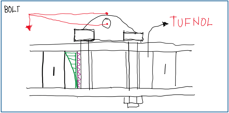
Assuming that this damper support is fixed bolt-nut fasteners. Usually bolts are made from strong materials, stronger than the insert one. As this is made from aluminum or carbon fiber, the solution is to make the bolt longer. A common approach when using bolts is to use one with its length of at least two times the thread, if the bolt is from aluminum. In case of magnesium bolts, this lenght could be three times higher than the thread. For example, if it is being used a M8 bolt, the thickness of the core should be two times eight, thus 16 mm longer. The problem with this kind of fastening is that the bolt-nut will compress the carbon structure and the core, which is made from a plastic, TUFNOL.
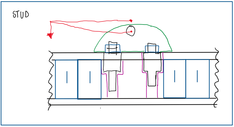
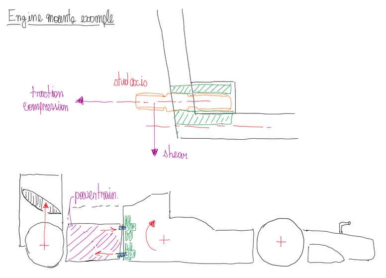
Since in the racing field the main concern is to go as light as possible, using bolts represents more weight. For this reason, studs are a better application, because it is possible to use ones made from strong materials, stronger than the nut. In addition, the stud is fixed in the insert as a bolt, but with adhesive for fasteners. The shank section of the stud can also have a bigger diameter to improve the resistance against shear stress, for instance, a counter bore stud (Figure 3). Another advantage of the stud is that the thread in the insert is not abused, because the only component which is removed is the nut. Hence, the insert is preserved.
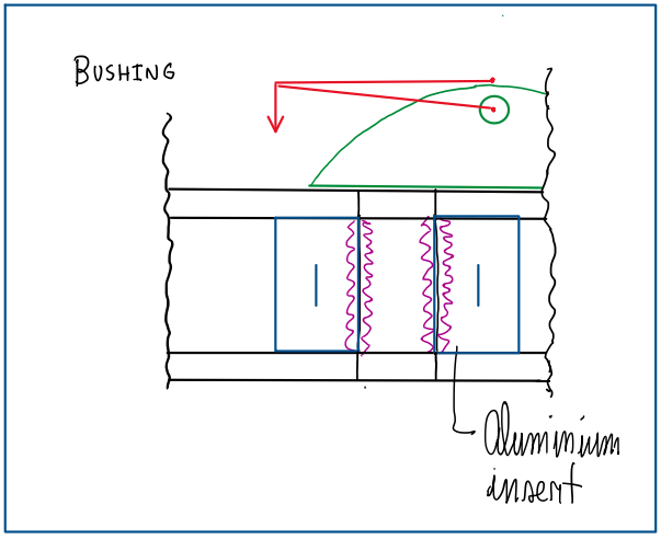
Another option is using bushings, more precisely, timeserts, keenserts or korbserts. Basically, the bushing is fastened in the aluminum inserts. An adhesive is used to provide a tight fastening of the bushing in the aluminum threads. Both bushing and insert are threaded. Some bushings have inner and outer threads. The objective of this approach is to provide a smaller and strong bore.
Carbon inserts
Carbon inserts are an alternative to metal inserts, they have some pros and cons. The thread made in carbon usually is higher that the hole. The fixing torque is ensured by a chemical locking additive. This is capable to hold the bolt while making the insert thread and the chemical bond the “same body”. The main advantage of the carbon inserts is its weight, they are lighter than aluminum inserts, 1.5 kg/dm3 agains 2.8 kg/d3 density of carbon and aluminum, respectively. Hence, it is possible to have a bigger insert. However, the problem with carbon inserts is the wear of its thread. In addition, the processes to build the thread, taping or drill, usually cut plies which are structural, which may generate a crack.
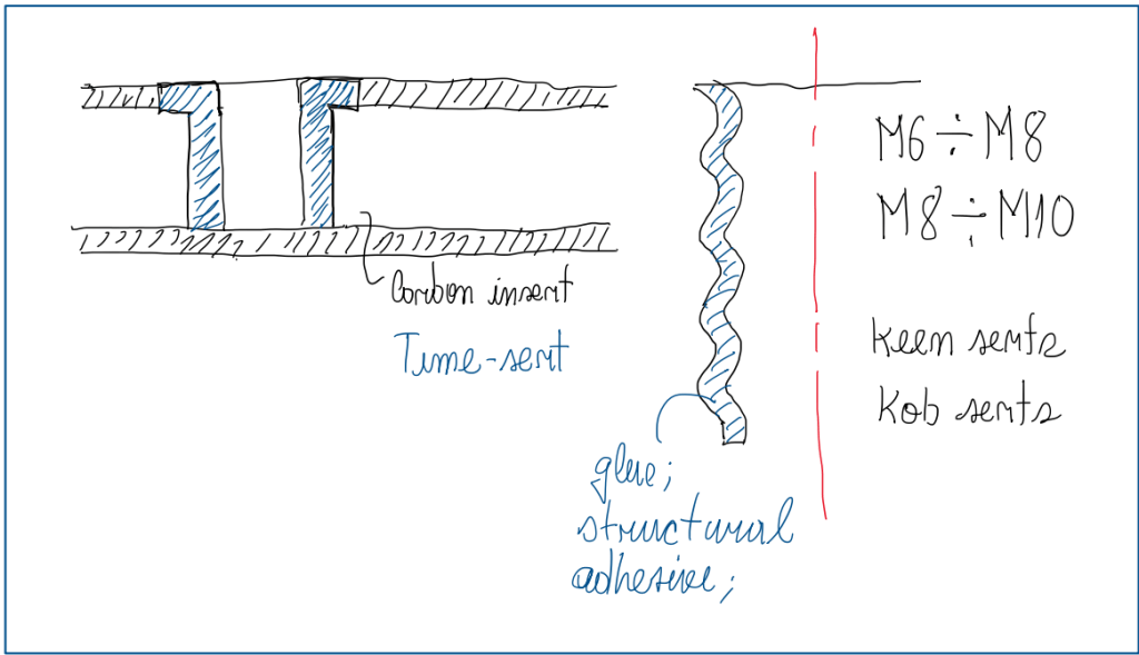
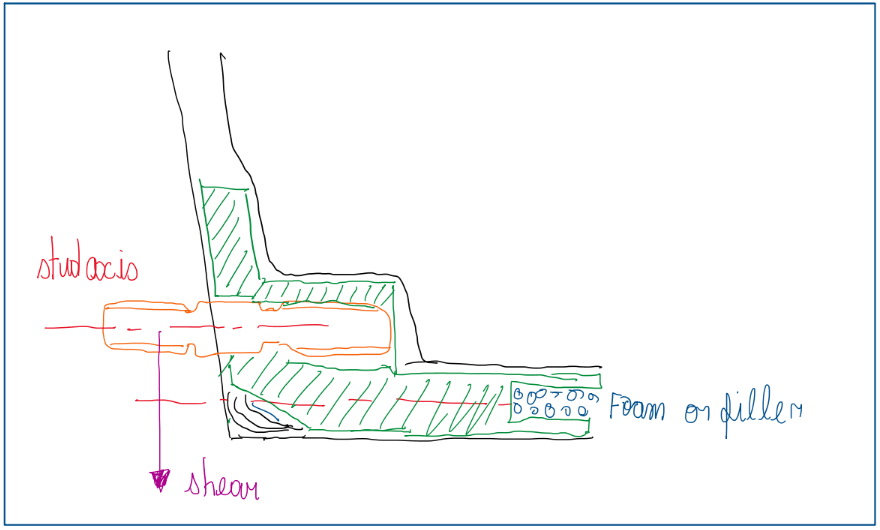
Figure 5 illustrates how bushings are mounted in carbon inserts. They are special bushings with inner and outer threads which are fixed fastening adhesives, keenserts or korbserts. In these cases, if the fastener size is M6, the bore must be a M8. In case of M8 fastening, the bore must be a M10. There is a small layer of adhesive between the bushing and insert threads. Since a carbon fiber alone has a low shear stress, this also represents a problem for this kind of insert. Considering a situation of a stud fastened in a carbon insert as seen in Figure 6.
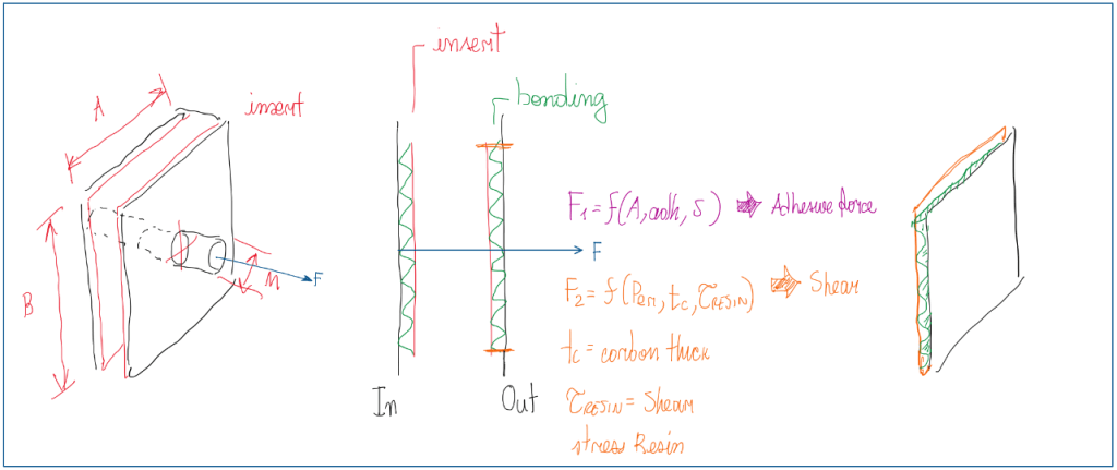
The main loads which this one is submitted is tension and shear. Understanding that the panel is composed by two skins of carbon, the insert is bonded between them (sandwich structure). Hence the force F1, which tends to pull out the stud, is the most critical one. This is a function of the glue or adhesive characteristics, the area which this is spread over the surface and the shear force developed between the stud and the adhesive layer. The other important load is F2 , it defines how strong is the carbon plies. In fact, these are submitted to this since the insert can destroy the carbon plies which would result in the total detachment of this one from the monocoque. Hence, F2 is a function of the shear stress of the carbon plies and their thickness. Another important factor is the perimeter, because shear occurs over it. For this reason the shear stress of the matrix (resin), not the carbon fiber, is so important.
Engine mounts
One of the main inserts built in the monocoque is the engine mount. As already known, in open wheels race cars, the powertrain has a structural function. Hence, the inserts used for engine supports are critical, because not only the engine is a heavy part of the car, as also vibrates. Therefore, engine mounts are inserts with the function of support the engine and absorb its vibration. The main problem that these mounts exhibit is the bearing load. Since the stud is made from high strength materials, this increase the shear strength in the insert. The result is that the bore of the stud became oval, which makes the stud loose. For this reason different strategies were developed to assembly engine mounts in the monocoque and these are summarized below:
- Carbon insert with metal barrel nut;
- Carbon insert with aluminum washer and steel nut;
- Carbon and steel insert with metal barrel nut;
- Aluminum insert;
- Aluminum insert with metal threaded bushing;
- Dowels.
These options also can vary according to the type of the stud used, which the conventional and the bottoming studs. Actually this is a strategy to better distribute the stress over the threads. Conventional studs concentrates all its stress in the firsts three threads, 50%, 25% and 12%, respectively. The bottoming stud has a protuberance in one of its extremeties. This is the side which applied in the insert and provides a more uniform stress distribution over the stud threads. Figure 12 and 10 illustrates examples of bottoming studs.
Carbon insert with metal barrel nut
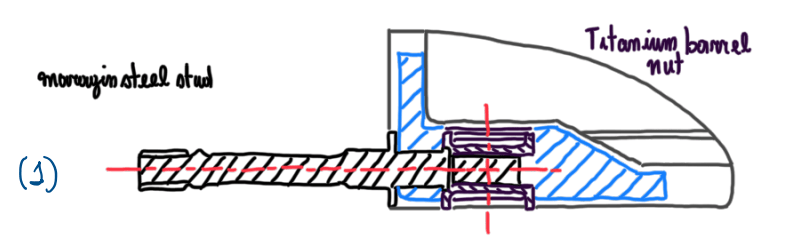
Carbon insert are very light and become a good option for engine mounts even though its low shear stress. Actually, a titanium barrel nut is used to connect the stud to the insert. The shape of the barrel nut improve the contact with the carbon plies, thus a better fixture after curing.
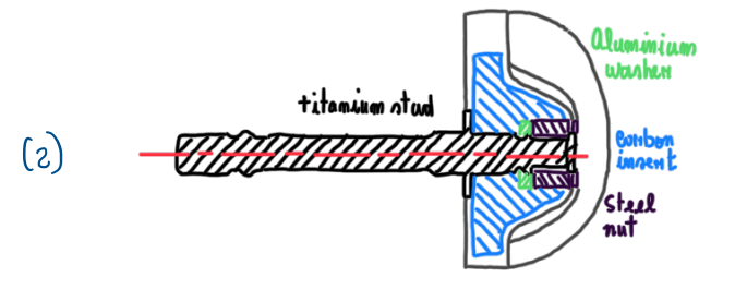
Carbon insert with aluminum washer and steel nut
Carbon and steel insert with metal barrel nut
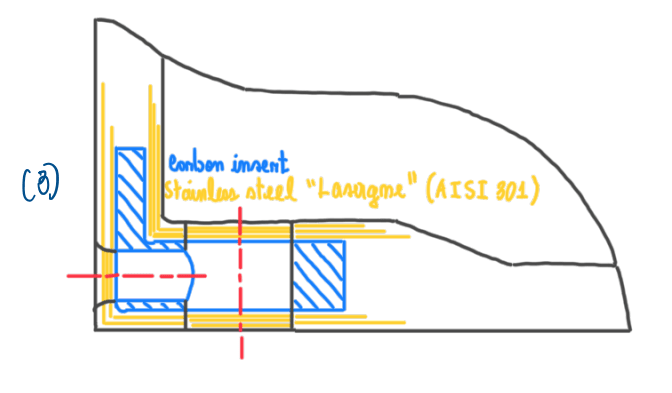
The lasagne structure is usually based in a mix of plies from carbon and steel, which are alternatively place one over the other. The objective is to increase the shear strength of the joint, since the steel plies represent and additional strength to the matrix. In fact, carbon plies have a low shear stress. Steel has a shears stress about 600 MPa. Another reason is due to what occurs when a stud is loaded as suggested by Figure 9. This leads to the so called bearing load, which makes the hole oval. A great increase of the strenght also increases the shear stress over the joint, because not only the carbon fibers are being stressed, but also the steel sheets. Usually race cars have between 4 and 6 studs to support the engine. These are highly loaded, but in a constant variation between tension and compression due to the load transfer during driving. These are conditions which the studs generate a bearing load on the inserts. This is the reason why some studs exhibits some play. The lasagne configuration with barrel nut is also a common strategy to avoid the bearing load.
Aluminum insert
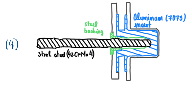
It is the most common insert used in race cars. A high stregth steel stud is not directly fastened in the aluminum insert, because this can easily wear its thread. To preserve the insert, a steel bushing is added. It can be mounted by thread or with adhesive. In any case, the stress from the stud is totally supported by the bushing.
Aluminum insert with metal threaded bushing
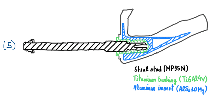
Similar to the previous example, but the bushing has inner and outer thread. To keep the bushing fixed in the insert an adhesive is used.
Dowels
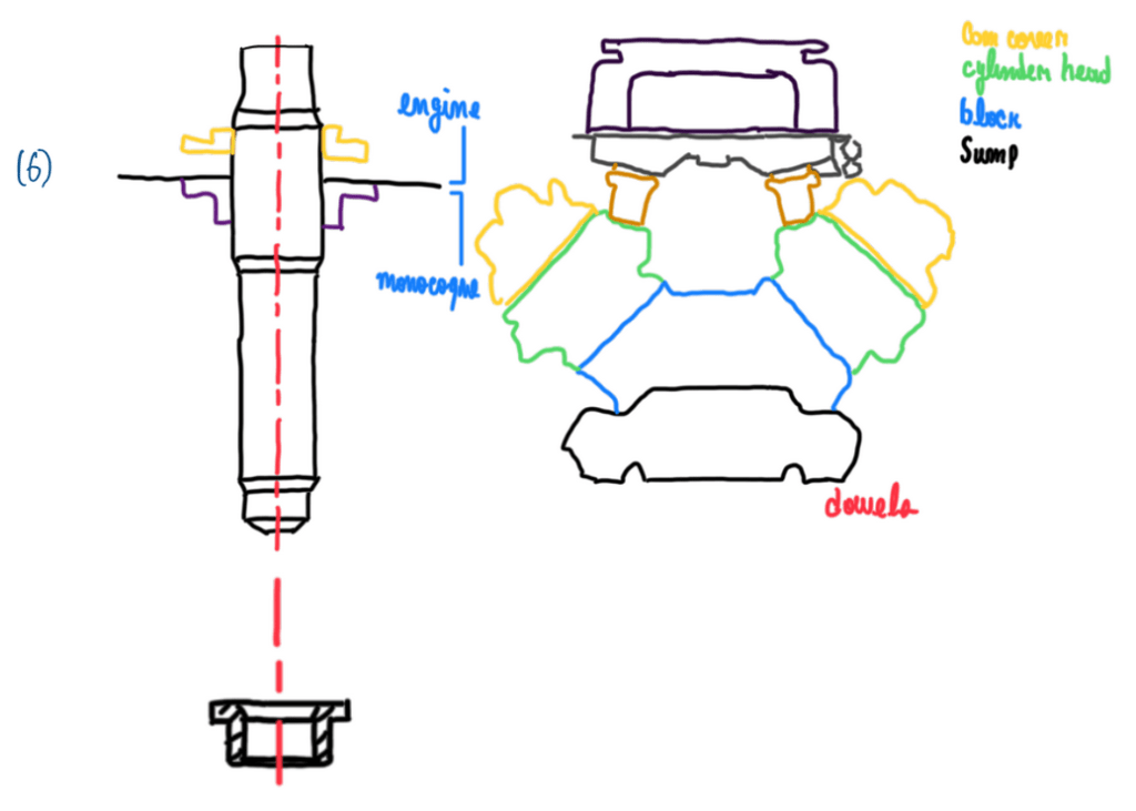
To auxiliate in the engine assembly it is common the application of dowels (Figure 11). These are basically bushings that locates the pins which come from the gearbox and bellhousing. Dowels are used for alignment and a precise location of the engine assembling on the monocoque and on the gear box. They are normally positioned at the engine sump or block.
Insert curing
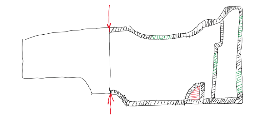
The best strategies to fix the engine mount, or any other important insert, in the monocoque, is to cure this one with the first skin. In this way, the inserts can be shaped according to the geometry of this region of the monocoque. Hence, a typical curing cycle is the 1st skin plus the main insert and the 2nd skin together with others inserts and the honeycomb, or any other core. This is an approach to use the insert as a seat for the carbon fiber. During lamination of the carbon plies in a mold, there are different plies which the wet or pre-cured ones, and the cured plies.
The problem is the thickness difference between wet and cured plies, that while the vacuum bag is squashing all the plies on the mold together with autoclave pressure, they can exhibit a problem called bridging. This occurs when the plies do not copy perfectly the mold. In Figure 14 it is possible to visualize a point which can occur the bridging. This is in the bottom of the structure near the insert chamfer. That region can exhibit bridging if the plies were not properly laminated. In fact, the occurrence or not of bridging requires very skillful operators.
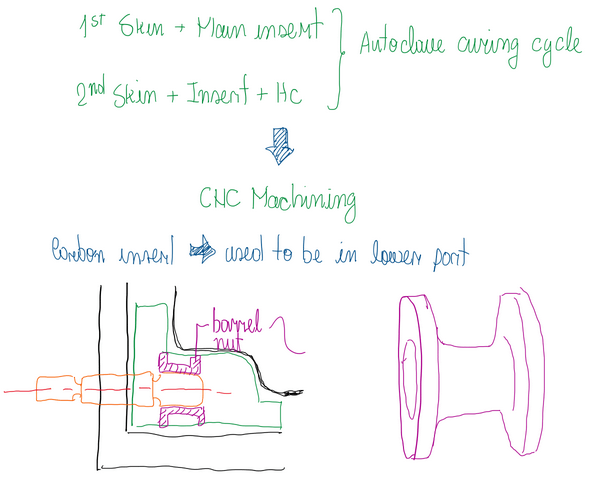
The barrel nut is cured together with carbon inserts. Previously curing, holes are built into the insert and the barrel nut is mounted manually, then the stud is also manually fastened. At some point the barrel nut is being compressed as the stud is being fastened. Hence, the barrel nut is fixed in the insert due to the stud fastening. The assembling stud and barrel nut is very strong, which is useful in lasagne strategy to support the bearing load. Barrel nuts are made from steel or titanium.
Reference
- This article is basically my understanding about one of the Chassi and Body Design lectures taught by Luca Pignacca and Gianni Nicoletto.
