
There are some variations of an anti-roll bar for racing application, but most of them is based in the combination of two springs acting in series. One of these is a blade, that activates the second one, a torque tube which produces a resistance per degree of rotation. The blade transmits the linear motion of the suspension to the rotation of the torque tube. The connection between blade and tube allows the rotation of this first one about its own longitudinal axis. This is used as adjustment which can be made by the driver during the race. Hence the spring constant of the torque tube changes as the blades are rotated, because their moment of inertia variate (I) with respect to the load at the tip of the blade.
Stress flow
The first important point in an anti-roll bar design is the understanding of the stress flow that this component and its parts are submitted. When activated by wheel loads, this results in a bending stress in the first blade. Since they are connected to the torque tube and even though there are several ways to connects a torque tube to the blades, their stresses are transmitted to the tube by a shear stress due to torque. This propagates along the entire length of the tube and reaches the other blade. As this one is fixed at its root to the torque tube and at its tip to suspension connections, usually a rocker, the blades will be exposed to a bending stress.
Anti-roll bar structure

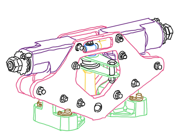
Figure 2 illustrates the anti-roll bar, which is a device that converts linear motion in rotation, thus it requires some important parts to supports this movements. Blades are usually made by CNC machined aluminum 7075 Ergal series. They are light, strong and CNC machining provides a very fast manufacturing. The torque tube is usually by steel or iron, due to their strength and enlogation capabilities. To provide support to blades, usually ball bearing are used, because they allow the blade rotation while supports a bit of axial and, mainly, radial loads. A needle bearing is also added at the root of the blade as an additional support to reduce friction in low speed movements, which is the case for blades. In addition, uniball is used at the tip of the blade to not only allow its rotation, but provides a connection to the push-pull cable, which is the device that makes able to the driver adjust the anti-roll bar during an outing. To guarantee the torque tube support, usually ball bearings are used. An important technological feature added to the torque tube is the spline, to connect the torque to the pin tube which is connected to the blade. This is an interface tube between the blade and the torque tube. Hence there is one pin tube at each torque tube. The anti-roll described at this paragraph is usually adopted in open-wheels race cars, which requires more compact components. An anti-roll bar for stock-car and touring car or any one based in road cars is bigger due to the own package of these vehicles, but the concept is exactly the same. In fact, the pin tube stiffness does not taken into account in the anti-roll bar calculation.

Another anti-roll bar concept is illustrate by Figure 3, it is used in hyper and super cars. As in open-wheels race cars, the package is critical and the components of the car usually have many function that requires a complex and compact shape. This is another concept which is composing by plungers, uniballs, counter-nuts, pre-load nuts, springs and low friction bushings. This concepts works with many beleville springs inside a housing which are activated by the plungers.

The plungers (Figure 4) are in contact with the uniball from a rod which is also connected to the suspensions. Hence, it is exposed to the wheel loads which angular displaces of the rod which activates the plungers. Pre-load and counter nuts regulate the amount of the anti-roll bar effect.
Anti-roll bar analysis
A good analysis was made by Crahan (1994) and it begins with the application of the Castigliano’s Theorem which defines that the deflection of the blade is the partial derivative of the total strain energy with respect to the load at the end of the blade, which is considered as a tapered beam. Hence, this is the reason why the sum of the strain energy from the shear and bending stresses are integrated along the blade length and it can be written in the following formula:

The deflection of the blade SBR for a unit load P is given by the equation in Figure 5, where k is the correction factor for the strain energy due to shear for a beam of rectangular cross-section which is equal to 1.5. “V”, “G”, “A”, “l”, “M”, “E” and “I” are the shear force, the modulus of rigidity, cross-section area of the blade, the blade length, the bending moment, the Young’s modulus and the moment of inertia of the blade at some point x along its length from the tip. Hence, it is possible to notice that this equation variates according to the blade cross-section area, b*H. Therefore, the moment of inertial of the blade at the point x can be given by the following formula:

Where “b”, “Hr” and “Ht” at Figure 6 are the thickness, the height at root and the height at the tip of the blade. This formula defines the anti-roll bar adjustment capability, since the torque tube thickness and stiffness is usually fixed. Hence, the deflection of the blade at its tip can be given by the following formula:

Since this formula has σbl and P, it is possible to find the stiffness of a single blade, Kbl:

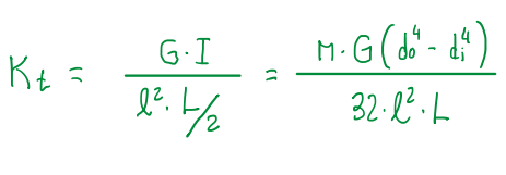
For the torque tube, its stiffness is based in a single formula for tubes:
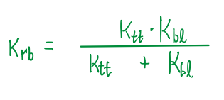
Finally, the total stiffness of an anti-roll bar is given by the following formula:
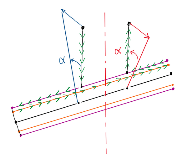
In addition to all these calculations there is an important detail about this kind of anti-roll bar, the effective length of the torque tube is just 1/2 of the true length L. According to Crahan (1994) this occurs because only 1/2 of the tube works for each wheel load. A couple is formed by the torque tube due to moments created in the extremes of it, which are equal but opposite. However, this is a condition that occurs when the system reaches the equilibrium, which is when the center of the torque tube has rotated by an equivalent amount to the difference between left and right travels (Crahan. C, 1994). Therefore, this is a condition equivalent to have just a half of torque tube being activated.
Sports car anti-roll bar analysis
This kind of anti-roll bar is usually used in super cars due to its size, since these vehicles has a critical package. This is very well fixed to the chassis, while the suspension push rods are connected to the rod between the plungers. As the chassis rolls, the springs are activated. The adjustments provided by the counter and pre-load nut provide some degrees of configuration.

There are some operation configurations in this kind of anti-roll bar which are summarized below:
- Case 1: No counter, no pre-load;
- Case 2: Pre-load, no counter-nut;
- Case 3: Pre-load and counter-nut.
Case 1: No counter-nut and no pre-load

This first case is characterized by the fact that both springs are free, in other words, they are totally extended. Hence, the stand-by condition is characterized by the simple Hook’s law, F = kx.
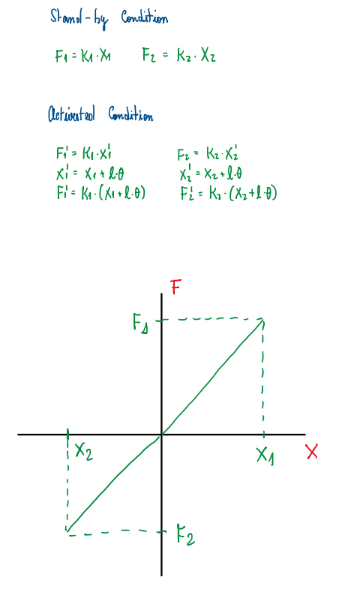
It is important notice that, when one side of the suspension is activated, just one spring is compressed. However, the other spring does not follows the rod, thus Figure 14 force and displacements illustrates that this configuration only operates in the quadrants 1 and 3. In other words, only one spring is activated at time when under wheel loads.
Case 2: Pre load, no counter-nut

Figure 15 illustrates ths second case. This condition provides a proportional variation of the equivalent stiffness. The springs are acting in some area of the second and forth quadrant due to the pre-load.
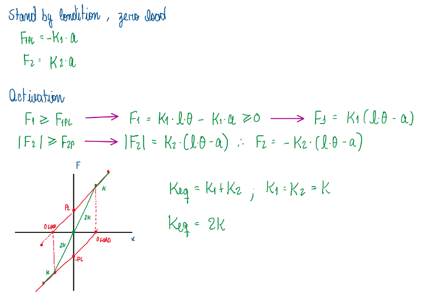
Therefore, the area of actuation was expanded (Figure 16). In addition, at some point of the operation, these bars are acting together. This can be observed with point of zero load of each spring being displaced to the curve of the other spring, it is possible conclude that inside the area comprised by the points PL, -PL and -0Load and 0Load, the anti-roll bar is acting in parallel ,thus, the equivalent stiffness became two times of the spring stiffness. After the spring compression overcome the 0Load point, the anti-roll return to operate with a equivalent stiffness equals to just one spring stiffness.
Case 3: Pre-load and counter-nut

With the addition of the counter-nut, the plungers are locked in their housing which connects even more their displacement to not only the wheel displacement, but also the the other beleville springs. In other words, in this case also have points of zero load (0L and – 0L) which the spring is already compressed. When the counter-nut is fastened, the plunger is displaced compressing more the spring. This creates a condition which the spring that is being activated by the wheel load also have an additional effect from the other spring. This occurs because the counter-nut lock the movement of the plunger during the spring back movement.
Motion ratio
The motion ratio is a very important parameter in the definition of the suspension kinematics. It means the ratio between the wheel displacement and the spring displacement. However, the displacement in physics has a lot o meanings, for a spring it is its stiffness. In a component analysis it also means the work developed by it. Since the forces acting on the wheels are known, by their displacements it is possible to identify their work. Considering that the work produced by wheels during movement is equal the one from springs, it is possible develop some relations.

Figure 18 illustrates that the ratio between the spring and wheel displacement is the square root of the stiffnesses. This is quite important relation, because in some situations it is not possible to define the wheel stiffness. However, with the well known spring stiffness and motion ratio of the suspension it is possible to obtain this value.
References
- This article is basically my understanding about one of the Chassi and Body Design lectures taught by Luca Pignacca and Gianni Nicoletto;
- Crahan, C. T. Modeling Steady State Suspension Kinematics and Vehicle Dynamics or Road Racing Cars – Part 1: Theory and Methodology. Society of Automotive Engineers – SAE, 942505, 1994.
