
Fasteners are usually used to fasten components which should be disconnected. This provides not only a mean for disconnection, but also a fast way to do it. In race cars this activity is even more critical and many options of fasteners are developed. The most known examples are bolts and nuts. To use them one of the components must have a tread which usually is machined. In race cars this could represent a roblem. As these are mostly made by carbon fiber reinforced plastics (CFRP), there are some methods to machine a tread in a carbon insert. Obviously this did not stopped the development of monocoques with bolts, but other solutions have appeared. The problem with carbon inserts is its wear due to fastening and unfastening many times. This constantly requires a process called taping, to cut again a tread in the insert. This article summarizes the main methods and fastening techniques adopted in the racing car design.
Rivets
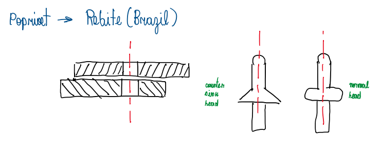
In some applications, fasteners must joint thin wall panels, which in race cars are usually the body work. For this kind of use, the pop rivet and the rivet nut are usually applied (Figure 1). Rivets are light and fast to be applied. However, it is destroyed when removed, thus it can not be used in parts of constant handling. The pop rivet only requires a hole on the component. It is composed by a shaft and a liner. At the top of the shaft there is a ball. When the rivet is applied, it requires a proper tool to be fixed. This one is fitted at the total length of the shaft outside the liner. When pressed, the tool pull out the shaft in order to squash the ball and to expand the shaft instead the liner. As a result, the rivet is fixed inside the hole and both components are joined. However, the application of pop rivets in carbon fiber structures do not work well.
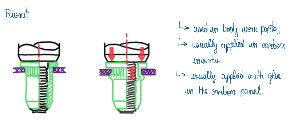
For these cases another kind of rivet is applied, the Rivnut (Figure 2). This is composed by a bushing which features a nerve at its top region. Inside the bushing there is a tread for the shaft, similar to a bolt, but without the head. The bushing is properly designed to be mounted on inserts and to provide a great contact area for the glue. The main application is for carbon fiber bodyworks. In fact, rivets are not good to be used in structural junctions.
Ensats
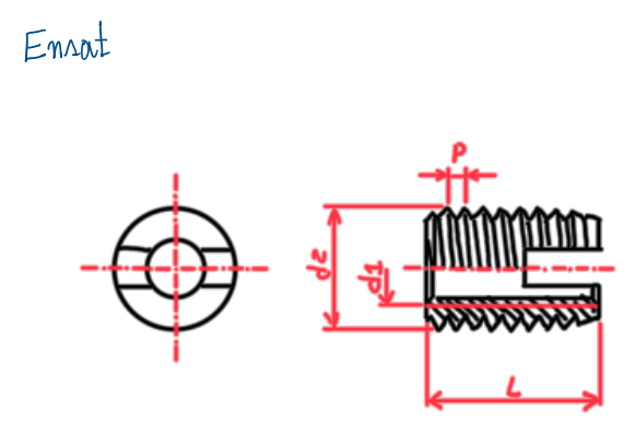
Since race cars are basically made by carbon fiber composites, the fastening used in this kind of material should be adjusted to the characteristics of CFRP. The problem is to guarantee that the tread will not damage the carbon inserts. The first fastening technique is called Ensat (Figure 3). A bushing with inner and outer tread is introduced in the bore together with an adhesive, usually a glue or resin. Both are efficient. Their difference is the curing. The glue use to cure after the fastening of the bushing while the resin can cure just in contact with atmosphere. These details change the assembling process. To fasten the bushing on the tread, a slot is machined on it. Actually, all ensats already came with this slot. The problem with ensat fastenings is their sizes. The bushing requires a too big outer diameter which not only requires more space, as is heavy. Although it is a good solution, it is not advisable to be used in top class race cars.
Time-serts

The time-sert (Figure 4) has the same principle as the ensat, but with additional features. The first one is the spot face, which helps to center the bushing position and reduces the stress concentration at the top of the fastening. Time-sert bushings are fixed by adhesives, but the inner part is cut by taping. In addition the outer tread requires a proper tool to be cut, this usually is provided by the fastening supplier. These features results in smaller bores and lighter bushings than ensats. In addition, the spot face feature provides also a good visual for the arrange. The outer diameter is not too high as the inner one in comparison to ensats.
Kobserts

These are a variation of the ensat for any fastening technique which uses an insert mean of fixture. It is mainly used in soft materials as carbon or magnesium. At the region of the hat, dents are machined to deform the main material when applied on it. They also avoid the rotation of the insert during bolt fastening. This kind of insert is used, because in soft materials it is common to occurs problems with tread wearing. The bolts adopted are usually made by steel which is stiffer than the material of the component to be supported. As a result, the constant fastening and unfastening wear the tread. For this reason, the inserts are made by steel. The kobsert requires similar inner diameter as ensats, thus they are big and this should be considered in the package. Kobserts (Figure 5) inserts are usually applied in gearbox casings and suspension pick-up points.
Keenserts

The keensert is a bushing which the tread is machined on it at the inner and the outer surfaces (Figure 6). However, together with these some slots are machined over the outer tread. These are used as housing for pins which are hammered inside the slot and the bore. Their function is to lock the keensert to avoid its rotation during fastening. The keensert is light and good for structural and body work components. However, when the pins area hammered inside, they damage the insert tread and may generate stress concentrations.
Livelocks

The livelock or livesert is a kind of fastening without tread insert. It is usually applied on bodywork panels (Figure 7). For these applications it is considered strong and very light. However, it is quite expensive, thus used in high level applications as Formula One. It is based in an insert with an allen bolt, this is fixed at the panels by the tabs. A ratchet works as a sound signal for the amount of turns given on the bolt, thus it works a reference for the technician who assembles the component or panel.
Cam locks
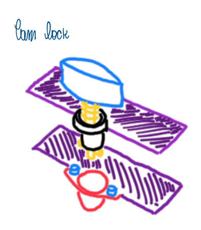
The cam lock mechanism (Figure 8) is similar to the livelock, but more simple and heavy. It is based in a pin inside the insert and a spring between them. This is always pushing the pin out of the insert. At the bottom of the pin there are cams which lock in the slots at the bottom of the insert, thus locking the panels. The way which the panels should open defines how the cam lock is considered open or closed. This technique is usually adopted in racing series which the budget is more restricted.
Dzus

Similar to cam lock, but bigger and with two springs, this the dzus (Figure 9). This insert is based in a bolt with big pace which when fastened it is locked by the spring. When the bolt is unfastened, the spring on the bolt or stud will pull it out as in the cam lock and live lock. The dzus is usually applied in bodywork. It is big, heavy and works well for shear stresses.
Studs
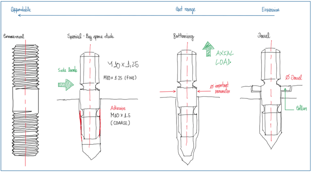
There are several types of studs used in race cars, they are usually applied to fasten components that exposes the structure to heavy axial, lateral and vibration loads which would be a great effort for a common bolt or nut. A stud is divided in three sections, two treaded and a smooth one, the shank. The objective is to avoid the high shear effort that bolts are used to be exposed, thus the smooth section of studs is carefully defined to hold the major part of the loads with the minimum of stress concentrations. The most common stud is the commercial (Figure 10), which is usually used for small components and parts. For instance, in uprights and monocoques, but they also work well as engine studs. The big spoke (Figure 10) stud has two different treads, a finer and a coarser ones. Usually, the coarser tread is used to fix the
stud in the structure or component that works as support, as the finer tread is used to fix the main component. In case of monocoques, big spoke studs are used with the coarser tread in inserts. In addition, adhesives use to be applied to fix this kind of stud, since they are exposed to big torques and jet nuts for fastening. These nuts expose the stud to big friction loads during its unfastening which could undo the stud. The big spoke studs are good to deal with high side loads. Another kind of studs is the bottoming one (Figure 10). This is applied for cases which the axial loads are the highest ones. For this, an extended body is provided, which is the reason why it is called bottoming stud. This helps to distributes the load to all treads, because when it has fastened, the bottom part of the stud is compressed in the insert. The dowel studs (Figure 10) are characterized by a dowel in the mid section of it. Hence it requires a spot face to house the dowel/collar. The objective is to precise locate the stud. In fact, dowel studs are suggested to be used whenever is possible, but their cost is the highest one. From commercial to dowel studs the cost can vary to 0.3 to 8 £.
Stresses in threads
During the design process the amount of loads that a fastener can hold is one of the main designer concerns. There are two main approaches, the conservative and common one and usually, the real stresses may oscillate inside the range between these two. The conservative approach considers that only one thread pair will take the entire load, while the common one assumes that the entire load will be equally distributed over all engaged threads. The reason behind the definition of theses assumption is that inaccuracies in thread spacing can lead the contact be concentrated at the first pair of threads. There three kind of stresses that fasteners are usually exposed:
- Axial;
- Shear;
- Torsional.
Axial stress
In the major cases the axial stress are due to tension, but some compression stresses can occur. The tensile stress area of screw thread can be defined by the following equation:

Where dp and dr are the pitch and the minor diameters. Finally, the axial stress in a bolt is given by the following equation (Figure 12):

Shear stresses
Another possible failure that fasteners are exposed is by shear stress. This can occurs due to the difference between nut and screw strength. Usually, the nut is the weaker component of the pair, thus the threads are stripped out of its major diameter. However, when the screw is the weaker component, the thread is stripped out of its minor diameter. Curiously, when both components have strong materials, the thread will be stripped out along the pitch diameter. In any case, the calculation performed of the shear stress assume some load share over the threads. The different assumptions are based in the materials used for nut and screw. In usual cases, the nut is made from a ductile material and the screw is stiffer and is assumed that all threads will be stripped out due to the equally load shared between them. In case of brittle materials for both nut and screw and poor thread fit, it can be assumed that each thread is entirely loaded until its failure and then the next thread will be loaded in the same way. The real condition is between these two cases. The striping-shear area for one screw thread can be written by the following formula:
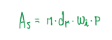
Where p is the thread pitch, wi is a factor that accounts the percentage of the pitch occupied by the metal at the minor diameter. However, assuming that the nut will be stripped out, the formula changes to (Figure 14):
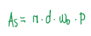
Which w0 is a labeled value according to the major diameter d. One of these cases is applied to the shear stress for thread stripping:

Torsional stress
Basically the torsional stress in a fastener is defined by the following equation (Figure 16):

This formula defines the stress that comes from the torque of a nut which depends on the friction at nut-screw interface. There two extreme conditions, the one which the nut is rusted to the screw. In this case all the effort will be absorbed by the screw. The other situation is when the interface nut-screw is well lubricated, less torque will be absorbed by the screw. Instead of it, the nut and clamped surface will retain major part of the stress. In any case, all the torque should be applied in the equation illustrated in Figure 16 as a conservative approach.
Bolts
Bolts are usually confused with screws. In facts they look similar, but the difference is in the fastening movement. Usually is the nut that is rotated along the bolt thread while the screw is what is turned to fasten the component. Usually bolts can exhibit a smooth shank or a completely threaded one. This last type can suffer from stress concentration due to the thread near the head, which is the point of highest stress. They are used in general machinery purposes. Similar to bolts, screws are usually adopted for high stress application, thus they have finer thread relative to bolts. There are many kinds of screws, from the Phillips to the socket hex head. A common class of screws and bolts applied in race cars are NAS ones. This means national aerospace standard and they have fine thread and dimple head hex.
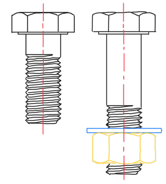
Nuts

There are many kinds of nuts, the basic ones are the hex nuts, which exists two variations, the standard and the jam ones (Figure 18). The jam hex nut is usually applied in pairs when the locking of the component is the main concern. In fact, the great problem of nuts is the their loosening when exposed to vibrations. For this kind of situation there are many solutions. For instance, the castle nut, which slots are machined in the top of the nut to allow a counter-pin to avoid the loss of torque. There area also the self-locking nuts. These usually have a nylon insert in the thread that deforms and fill the thread clearances and locks the nut after fastening. Another type of locking nut is the jet-nut. This one has an elliptical shape in the firsts threads, which provides an interference with those on the bolt or stud. As soon this nut is forced, the friction at the thread interface resists against the loosening.
Washers
Basically, washers are used to increase the contact area between the bolt, nut or screw and the clamped part. However, there are some different washers according to the application. For instance, bolts or nuts used in components with sensible electronic system could be provided with insulated washers. There are also Belleville washers used when it is required some control of the axial forces when the bolt
variates its length. Fender washers usually a have a greater diameter than the standard one. They begin to be applied in the automotive industry to fix parts made by sheet metal, as fenders, reason of their denomination.
Bores
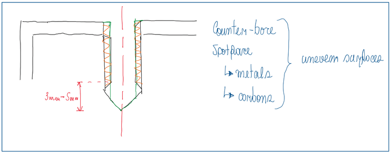
In a monocoque sometimes a hole must be tapered. The problem with this is the stress concentration at the surface (Figure 19). For this reason, some solutions are proposed. For instance, a counter-sink hole, the counter-bore and the spot-face. These can be usually applied in metals or carbon fiber inserts. The critical applications is the last one. The tapping process can not be done in order to tread the entire hole. In fact, the tread must go until 2 – 5 mm from the end of the hole. The reason for this is the perfect seating of the bolt. The manufacturing process of this hole is composed by a drill and tap. The drill cut the material and opens the hole, which will treaded by the tap. However, due to the stress concentration at the surface, some machining is required.
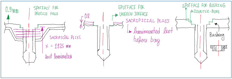
The main problem to machine on carbon is that it remove plies which can weak the structure in that point. To avoid this it is added some extra layers of plies whose are called sacrificial plies. In general the spot face is differently applied. For instance, there are cases which the hole must be precise and the surface should have a good finishing. Hence, sacrificial plies are laminated between the structural ones. The main concern of this approach is if the hole cracks, thus the stress will be transmitted to the structure. For this reason the sacrificial plies are placed around the hole and between the structural plies. When the surface is uneven and there is no requirements for a rigid tolerance, the sacrificial plies are laminated over the structural one to preserve them. Another kind of bore is the spot face and the counter-bore together. The objective of this second feature is to provide a precise location for the bore, thus a precise bushing is fitted in the counter-bore. In this way the advantage of the spot face and counter-bore are combined to provide a strong and precise bore. It is usually used for fastening of engines or components that requests a rigid tolerance for their position.
Corrosion
Since most of the fasteners are metals, they are exposed to corrosion. The are some variation of these processes, but the main ones are:
- Galvanic corrosion;
- Crevice corrosion;
- Pitting corrosion;
- Stress corrosion cracking.
Galvanic corrosion
It is a process that usually occur where there are two conductive materials in contact and in presence of electrolyte. In fact, this process is derived from the phenomena that occurs when two conductive materials in electrical contact are expose to an electrolyte. A current flow between them and is called, galvanic current. Hence, the galvanic corrosion occurs in the anodic site of this pair. This current follow the Faraday’s law. Just 50 mV potential difference are enough to initiate the corrosion process. There are many factors which can motivate a galvanic current, thus corrosion. Usually, the potential differential between the materials is the main one. However, geometrical aspects of components in contact, environmental conditions, metallurgical factors, surface conditions, electrolyte properties and the reaction also define the rate which the corrosion will occur. A common method to avoid the galvanic corrosion in fasteners is using washer and gasket as a way to insulate the metallic components. In addition, a coating, such as black oxide, phosphate or zinc plating is effective. Another important field
which the galvanic corrosion can occur is in parts and components of unibody. Since many of these are made from high strength steel and aluminum, they require a joint technique that avoids galvanic corrosion. In fact, the use of non conductive adhesive provides an insulator together with the bonding. In addition, there are self-piercing rivets, clinches or rolled hem joints. The advantage of adhesive is that they also works as sealing against possible electrolytes.
Crevice corrosion
Similar to the galvanic corrosion, the crevice one occurs when the concentration of gradients of chemical species involve in electrode reaction are formed. For instance, in regions of the assembly where the same component is exposed to different dissolved oxygen concentrations. Usually, the cathode is the region where there is a high concentration of oxygen and the anode is the one with the lowest oxygen concentration. This phenomena gains force when the component under corrosion process has suffered from passivation, which is a metal surface protection that uses its own oxide due to a high oxygen content. Usually, in cars, the crevice corrosion occurs in fasteners and under paint.
Pitting corrosion
The pitting is a process that is activated after an initial damage that broke the oxide film and the protective coating. It is also possible that chemical in-homogeneities in the metals triggers the process. There are also chemical factor that can damage the oxide film as low oxygen concentration and high chloride ion concentration. In fact, a chloride solution is also required for this process propagates faster.
Stress corrosion cracking
This is one of the main corrosion failures that a car exhibit. A failure that initiates in the grain boundary due to a high static stress and an environment of chlorides. The previous corrosion processes can also works as a trigger for SCC if the other factors are also occurring. Usually SCC occurs in stainless steel and aluminum. The first exhibit SCC if the factors listed occurs, except the ferritic stainless steel that do not suffer from chloride induced SCC. The aluminum components suffer from SCC if they have as alloying elements, Cu, Mg, Si and Zn. The SCC failure stress can be far below the yielding stress when all factor are acting over the material.
References
- This article is basically my understanding about one of the Chassi and Body Design lectures taught by Luca Pignacca and Gianni Nicoletto;
- Norton, Robert. Machinery Design, McGran Hill, 4th Edition.
