
Different from road vehicles, race cars can not run as fast as possible without some control over its fluids. There are some reasons which justify the development of a proper lubricating system for racing cars, these are:
- The high lateral and longitudinal accelerations developed;
- The center of mass height reduction.
The first reason is the high g developed by high level race cars. This generates big displacements of fluid inside the engine block and oil tank. The consequence is the concentration of oil in the engine crevices which results on loss of pressure. In other words, some parts of the engine operate without enough oil, which can be catastrophic if it is considered that these engines can rotate at 10,000 RPM or higher. Another reason is that race engines are becoming smaller and smaller, and race cars are kept as light as possible, as low as possible and as wide as possible. Hence, the race engines are also the target of the weight reduction and packaging which reduce its height from the surface. Usually, high level race cars have the height from the crankshaft until the track surface of just 100 mm. One of the measures to obtain this configuration is the reduction or removal of the engine sump. Engines without sump operates with the so called dry sump lubricating system, which has a proper lubricating oil circuit composed by several components. The objective is to guarantee uniform pressure under the entire outing. In addition, the dry system makes able to engine operates at higher temperatures, which can also be another reason for its application. Therefore, the circuit of a conventional dry sump system is composed by
- Pump;
- Scavenge pump;
- Oil cooler;
- Tank;
- Catch tank;
- Pressure relief valve;
- Filter.
The system enters in operation together with the engine, a scavenge pump drain the oil from the engine sump and sends it to an oil tank. This has not only a function of a reservoir, but also to separate the air from the oil. Although the lubricating system operates without air, it is atural that there is some air in the system, because there are some points of air entrance on it. Hence a decanter is applied at the top of the oil tank. This is called swirl pot and it is usually at the top of the oil tank. The oil pump absorbs the oil from the tank and send it to the engine at high pressure. Different from road cars (without dry sump system) the oil pressure reaches values above 6 BAR. Finally the scavenge pump absorbs the oil from the sump and send it to the tank, thus the cycle restarts.
Dry sump lubricating system features
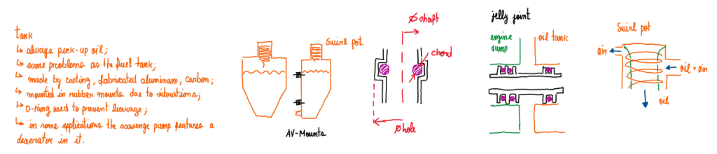
The oil tank usually exhibits the same problems as the fuel tanks, thus its shape is defined to always pick-up and provide oil from the de-aerator and the pump, respectively. Usually, the oil tank is made by casting metals, carbon fiber composites and fabricated aluminum. F1 and WEC series adopts the carbon fiber construction, since the main focus is weight reduction. Another series likes F2 and F3 usually use more simpler construction as fabricated aluminum. The de-aerator is a device with the objective to remove air from the oil. This is done by the centrifugal force that act in the oil. The oil plus air enter in the swirl pot (Figure 1) and the circuit exert a high centrifugal force over the fluid that separates the air from the oil. Hence, this goes straight to the oil tank, while the air take another duct. In the past this path was basically the expulsion of the air to the environment. However, since this is part of the emission regulation restrictions, this air is conducted straight to the engine intake to be burn in the combustion chamber. Due to the return of turbo-charged engines, this can not be anymore burned by the engine. Although this air comes from the de-aerator, there is some amount of oil in it. This would be burned in the turbo which drastically reduces its durability. The connection between the oil pump and the oil tank is critical point of this system, because it is highly exposed to the vibrations of the car.
Dry sump lubricating systems evolution

During nineties it was common to put the oil tank at some different places as the gearbox casing. In this configuration, a tube must connect the tank to the pump and this is the most critical point (Figure 3). Since many teams during that period did not have a proper quality control, it was easy to have some dimensional variation in some components, mainly the fabricated ones. One example is the joint that connects the tank to the tube which is connected to the pump. Dimensional variations on this component result in problems with oil pressure when the demand is the highest one. In other words, at high speed and high lateral g sections of the track. This can be visualized by the data acquisition system. The analyst or the track engineer decide if the driver can continue or not. Nowadays, this configuration is obsolete, the oil tank is positioned behind the fuel tank. Even though this is a better position for this component, it is also critical, because the package of the fuel and the oil tank is very strict. Hence the oil tank must be very well fixed and protected against vibrations. Since race cars vibrate a lot, due to surface imperfections, kerbs and some shunks. Any fixture under vibrations will break if not proper fixtures were used. In fact, for oil tanks these are made with together with rubber mounts for vibration absorption. Another important point is about the center of gravity. When under vibration, the oil tank moves and this disturbs the center of gravity.
References
- This article is basically my understanding about one of the Chassi and Body Design lectures taught by Luca Pignacca and Gianni Nicoletto.
