
What race and road cars have in common ? Both have four wheels. Beyond this fact, everything is different. It can be said that race and road cars design is similar in some aspects, because many technologies and engineering tools in automotive field either are derived from aeronautics, or from racing field. The main racing series, F1, had your moments that usually export technologies directly to road cars, as sequential gear box and active suspension. However, F1 car are usually called open wheeled ones. They are characterized by a fit and lightweight body and by wheels. This kind of car became synonym of race car. Although they look similar each other (F1, Indycar, F2 and F3) they have a lot of differences. Therefore it is important to understand how and which are the components of an open wheel race car architecture. Basically, these cars are split in different systems that are no equivalent to the road going cars. The main systems are:
- Chassis;
- Bodywork;
- Suspensions;
- Powertrain;
- General systems.
All of these have one common characteristic, they are designed to have the highest performance with the lowest weigth.
Chassis

The main component of a race car, it defines the torsional stiffness and safety. The chassis is divided in subsystems:
- Monocoque;
- Front impact structure;
- Side impact structure;
- Rear impact structure;
- Bell-housing;
- Gear box casing.
The monocoque is usually made by carbon fiber. It concentrates the most part of the chassis torsional stiffness. Its main function, besides torsinal stiffness, is ensure the driver safety during impacts which can occur in race tracks. The carbon fiber provides the stiffness and also the lightness, usually the main composites are T300, T700 and T800 carbon fiber composites. Attached to the monocoque there are impact structures, bell-housing and gear box casing. As the name suggests, the impact structures has the function of absorbing the impact energy. Usually, carbon fiber used is a composite with more ductile behavior, that is able to work in low and high speed impacts. In other words, providing fiber cracking and delamination when convenient. A front impact structure is the nose box, the side ones can be the side pods, but usually there are some tubular structure at this part. The rear impact structure is made by the same material as the nose box, but in this case is behind the gear box casing. Its function is to collapse is to collapse in case of rear impacts. The bell-housing is an intermediate component between the engine and the gear box. As some racing series uses different engines for the same gear box, this requires different mounting points for each engine. An unique gear box casing is required for each engine, but also increases the costs. The bell-housing is different for each engine, but has the same mounting points on the gear box. Both components are usually made by cast aluminum, cast magnesium or CNC machined aluminum. The casting process adopted is sand casting. In some specific cases, investment casting. The main materials used in the chassis structures are carbon fiber reinforced plastics CFRP, which are T300, T700 and T800. There are some parts of the monocoque that are made by Aramid, Kevlar, Zylon, and Dyna. In the monocoque there a lot of inserts for bolts, screws and studs. The inserts are usually made aluminum 7075 Ergal seires, a very stron and light aluminum alloy.

Figure 14 illustrates an aluminum inserts are cured together with carbon fibers. In addition, the thread for the bolt is done in the region of the insert that there is more material to provide support for it. Although in the Figure 14 it is illustrated a bolt bore, could be a stud one. Another important detail which can be noticed is the honeycomb aluminum insert (Figure 15).

The honeycomb is a structure similar to a bee nest, which is the reason why this aluminum layer received this name. Its main objective is weight reduction without decreasing of the cross-section area. Moreover, it is possible to visualize another layer of aluminum between the carbon fibers (Figure 15).

Although CNC machined aluminum are mainly used in the monocoque, there are also low cost options, as cast aluminum. Figure 16 illustrates an example of insert made from this technology and its design has interesting strategies. For instance, at the extremities there are tabs, these are designed to increase the contact area of the insert with the carbon plies during cure. The region with the greater amount of material is the one which is drilled the bore for the bolt.
Monocoque
The monocoque is also called the survive cell. In fact, this is its main function. It is a unique structure made from carbon fiber, aluminum (Ergal-7075) inserts and light fillers as aluminum honeycomb and Rohacell. The main concern about it is its mass, for this reason these materials are used in structure which are designed to have a highest inertia moment as possible. Although monocoques are very strong, some decades ago series like F-Nissan and Superformula were evaluated relative to safety by crash tests. These are done in some points of the monocque. One of them was the side impact, also called T-crash, the most dangerous impact that a vehicle can suffer. The objective is to verify how strong the structure against a lateral impact. The result was the complete penetration of the trolley in the monocoque. Although the monocoque under test was using strong aluminum buckets at the sidewall, the damage was critical.

The solution for these is still in use, a layer of anti-penetration material. As seen in Figure 1, 16 plies of Zylon and 7 plies from Kevlar (Aramid). The layer of Zylon is about 16 – 17 mm thicker, while the kevlar one is 3mm thicker. However, to guarantee the driver safety the car constructor must ensure that a lateral impact will be well distributed over the lateral are of the monocoque. There are four quadrants whose the impact must be spread.

The carbon fiber has the characteristics to behave differently when under static and dynamic loads. The problem with this area is the sidepod and the radiator which are mounted there. When the monocoque was hit by another, the sidepods allow the passage of the monocoque for perfuration. This hits the quadrants just in the middle which make an open and allow the perfuration. The modification proposed was to work with 2 bigger quadrants which was a better package solution for the radiator. In fact, even the experiments with carbon fiber components are complex, because these under destructive tests behave differently when these are static or dynamic ones. The fracture mechanism is completely different at these conditions and can generate a quantitative difference, about 30%.

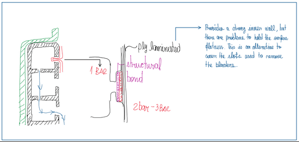
After FIA decision to no test the side bars, the teams must develop these according to a defined regulation, a side bar assembling was developed by RedBull together with FIA. Teams now must follow the dimension and features of this new component, submit their components to validation tests and only after approval they are allowed to use. This new side bar (Figure 3) is based in an aluminum beam, re-shaped side bars and a reinforced step-floor. The aluminum bar is inside the carbon fiber structure and protect the driver above his/her shoulders. The re-shaped side bars have their structure well defined by a ply-book. This is a document which has the complete information about the material, orientation of the plies and composition. In addition, these side bars have extra plies to reinforce the structure.
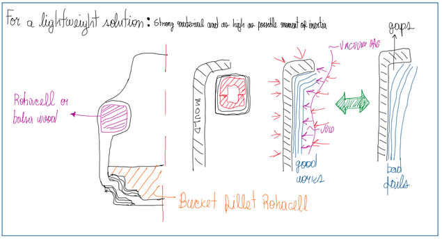
The objective in Formula One is to reduce the weight to as low as possible. Hence, this beam became one of the main targets. In fact, there are some solutions for that region. For instance, Rohacell was commonly used in F1 cars, some other open-wheel vehicles had adopted balsa wood. Although both are very light, the first make the structure stronger. There are two means for this, using stronger materials and/or increasing the cross-section area, which means, increase the inertia moment (Figure 4).

Although a new material usually add weight and a bigger cross-section area means more material, a hollow one is a great solution to reduce weight. Hence, a section of Rohacell was first substituted by a smaller one, and then, a complete hollow section. The manufacturing process to obtain this shape is complex.
The section with Rohacell was removed is a critical point during the lamination process. The operator must make sure that the plies are well compacted, or rather some voids will result in a quality rejection. If the operation is well done, the vacuum bag will be able to provide a balanced pressure over the plies. In the hollow section a silicon mold is used relatively filled of air to provide a good lay-up around the hollow shape.
Gear box casing

The gear box casing is a component mounted at the rear part of the car. In race cars it even has a structural function, since the suspension arms are fixed on it. For this reason the material used should be light and strong. The steel is too heavy, despite its strength. Aluminum or magnesium are good options, because they are light and reasonably strong. This helps to provide components with thin walls, which there is a great impact on weight and strength. Since this component concentrates many functions, its shape is complex. Hence, the sand casting process is usually adopted, not only because it allows some shape complexite, but also due to the high castability of aluminum and magnesium.
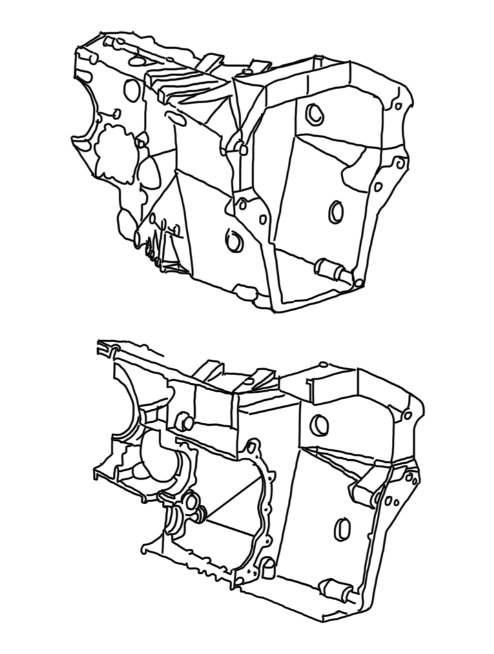
The Figures 10 and 11 illustrate an example made by sand casting, finished by CNC machining and applied for a high level race car. The material is aluminum due to its good castability and formability. This casting process has two sand molds which has the negative parts which are the half of the gearbox casing vertically split. These are made by resin negative pattern which pressed against the sand by huge pressing machines.

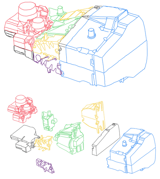
The main problem of this process is to create the inner volume of the gearbox casing. For this, parts called cores are used to, not only define the inner volume, but also the wall thickness. In fact, cores define where there is metal, where there is not. Due to the complexity of a race car gearbox casing geometry, the core is split in several parts called boxes (Figure 13).
The gearbox casing not only provides housing to its components, but also to the suspension arms, anti-roll bars, rockers and the rear wing structure. Hence, many different loads acting on this component that result on a great influence on the total torsional stiffness of the car.
Materials summary
The materials used in the manufacturing process o a race car (open wheels or LMP race cars) are:
- Carbon fiber reinforced plastics (CFRP);
- Kevlar reinforced plastics (KRP);
- Zylon reinforced plastics (ZRP);
- Aluminum 7075 Ergal;
- Heat tretable steels: 15NiCrMoV6, 25CrMo4, 38NiCrMo3, 42CrMo4;
- Case hardening steels: 18NiCrMo5;
- Maraging steels: C300;
- Titanium: Ti6Al4V;
- Structural foams: Rohacell, Balsa wood and Termanto;
- Honeycomb: Aluminum 7075 Ergal or Paper.
Monocoque manufacturing cycle
The manufacturing process of a monocoque has many steps, it begins with the process of tooling, which is basically the preparation of the molds. It comprises the pattern work manufacturing. This is building of the pattern which made from epoxy resin. Beyond the preparation of the resin, there is also the machining of this one to form the negative of the pattern. Meanwhile the carbon mould manufacturing involves the curing of the carbon layers laminated, usually at 50 C. When the pattern and the mould are build, the tooling process is finished. The next step is the lamination of the carbon layers in the mold. This is critical process, because it request a very skillful operator. Lamination is a manual process which carbon plies are placed in the mould, then pressed against it to have the maximum contact with the mould as possible. This is extremely important for the curing process, which vacuum bags and autoclave pressure will heavily press the plies against the mould and then they will form the part. If the lamination is not done properly, it is possible that the carbon plies do not follows totally the mould. The result is a problem called bridging, which is when parts of the ply do not fully adhere into the mould. Finally, after curing, the CNC machinig process is performed to cut edges and to give some finishing to the component. In addition to this final trim, there is also the bonding of the components. The main advantage of the carbon fiber composites is the possibility to design a new material for each component.
Monocoque design summary
The development process of a monocoque is based in the factors summarized below:
- Regulations: They define the shapes, homologated loads and the crash tests.
- Car general layout: The design office and the aerodynamic department define the layout of the car. For instance, the shape of the rear and front wings, the side pods and engine position.
- Loading definition: The vehicle dynamic department basically defines the mathematical code of the vehicle and also calculate all the loads which the car must hold;
- Shape: Some racing series defines a common shape for the cars. In fact, these are one-brand racing series. Hence the car maker defines the shape of the car according to its philosophy. However, the shape of the vehicle monocoque is directly connected to the characteristics of the composite materials and the results from the finite element analysis FEA.
- FEA: It calculates the effort on the structures, in other words, plies. Parameters as safety factors and failure criteria (Tsai-Wu) are defined in FEA;
- Ply-book redaction: The department of materials and composites specialist write a document called ply book which basically defines how the monocoque and carbon fiber components are built;
- Bio of material: The design office defines what is considered as the most important document in for entire car design, the bio of material. This is a giant data file which archive all drawings and CAD with all information about it. For instance, the amount of a specific component in the car, from which material it is made, the supplier of the component/material, assembling procedure, manufacturing and machining procedures.
How the company will conduct all these processes and important factors are mainly defined by the budget dedicated to the project and, specially, the calendar. Every year there are many racing series beginning their seasons, this means that there is no delay. The project should be completed at time enough to ensure proper testing, validation and delivering of the cars to the customers.
Chassis torsional stiffness
This is the main performance parameter of a chassis. However it is important to understand until which point the monocoque influence in this parameter. Assuming a simpler chassis configuration:
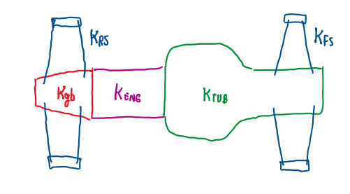
Figure 7 illustrates that in an open wheel race car the chassis torsional stiffness is given by the stiffnesses of monocoque Ktub, the suspension arm Kfs and Krs, the engine Keng and the gearbox Kgb. It is possible to admit that the suspension arms are the most flexible components and the engine is the stiffest one, because it is short. Hence, a great improvement in Ktub may not result in noticeable in improvement in the total stiffness of the chassis, Kt.
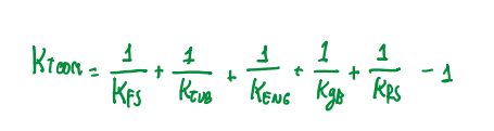
The total torsional stiffness can be calculated according to Figure 8, which describes the chassis a parallel spring combination. An approach to evaluate the monocoque, is fixing this one a rig which performs its torsion. In addition, using solid links in the place of coilsprings and suspension arms will isolate the monocoque which makes the experiment more precise (Figure 9).
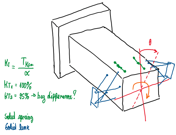
After this test it is possible to conclude that, the total stiffness chassis will not be obtained since the suspension components are not rigid, even though the monocoque is as rigid as possible. Hence, the suspension arms are the main source of compliance. In addition, sometimes can be more important the stiffness of the anti-roll bar pick-up points than the chassis torsional stiffness. Another important detail is, the driver is not able to determine if the chassis is not stiff enough, since it fells the stiffness of the entire car, not the monocoque alone.
References
- This article is basically my understanding about one of the Chassi and Body Design lectures taught by Luca Pignacca and Gianni Nicoletto.
