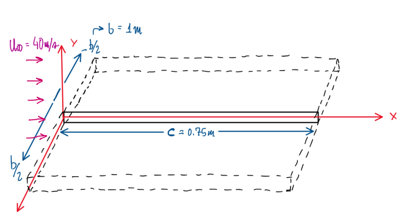
A flat plate is imersed in : an airflow of u∞ = 40 m/s, it has a spanwise b = 1 m, a chord c = 0.75 and it is placed paralelly to the airflow, x-axis. The y-axis is pointing upwards. The x = 0 coordinate is at flat plate leading edge, while the coordinate x = c coincide with the trailing edge. The spanwise coordinate z ranges from -b/2 to b/2 respective to the wing edges. This exercise is divided in three sections.
First section
The first section is base in three calculations, (1) the vorticity at the upper surface at point (c,0,0) for cf = 0.003, (2) the airflow rate at the boundary layer in m²/s for (x = c, z = 0) and y > 0 with δ = 0.016 m and δ* = 0.002 m and define (3) an analytical expression for the airflow rate at (x = c, z = 0) and y > 0 where the velocity profile is given below:
u = u∞∙(y/δ)1/7
The first step is to calculate the Reynolds to identify if the airflow is laminar or turbulent:
Re = u∙l/ν = (40 ∙ 0.75) / 15∙10-6 [(m/s) ∙ m/(m²/s)] = 2000000 = 2∙106 → Turbulent flow
Another important calculation is the dynamic pressure, is most of the aerodynamic questions it is necessary to calculate this parameters, which is given by:
q∞ = (1/2)∙ρ∙u∞² = 0.5 ∙ 1.2 ∙ 40² [(kg/m²)∙(m/s)²] = 960
Question 1
Hence, considering a turbulent flow it is possible to start the vorticity calculation (1). Actually, the fact of the turbulent flow is one of the considerations. Since this question supposes a flat plate with a negligible thickness, the vorticity is calculated assuming that the airflow is close to the plate where there is no slip conditions υ|ω = 0 are applied. Basically, these simplify the calculations considering a 2D flat plate, which implies:
∂u/∂y ≫ ∂υ/∂x
Hence, the vorticity can be simplified to:
ω = (∂υ/∂x – ∂u/∂y) ≈ – ∂u/∂y
However, the velocity component u is not known (for this question), it is necessary another mean to calculate this. For a streamwise direction x, wall-normal direction y it is possible to write:
τ12|ω = 2μS12
Since the Prandt magnitude order of analysis approximate this to:
τ12 ≈ μ∙(∂u/∂y)
At the wall (y = 0) this approximations is not anymore required, thus:
τ12|ω = μ∙(∂u/∂y)|ω
The shear stress at the wall can be very often given by:
τ12|ω = τω
The local friction drag coefficient is already known, thus using its definition it is possible to find the vorticity:
cƒ(x) = τω(x) / q∞
τω(x) = cƒ(x) ∙ q∞ = 0.003 ∙ 960 = 2.880 Pa
τω = μ∙(∂u/∂y)|ω = 2.880 Pa → (∂u/∂y)|ω = 2.880 / μ = 2.880 / (18∙10-6) [Pa/(Pa∙s)] = 160000 = 1.6∙105 s-1
Thus:
ω = – ∂u/∂y = – 1.6∙105 s-1
Question 2
The next question ask to calculate the airflow at the boundary layer in m²/s for (x = c, z = 0) and y = 0. If one of the informations is δ = 0.016 m and δ* = 0.002 m, the displacement thickness is being considered. For a flate plate case and assuming a constant density, the volumetric flow flow rate due to the displacement thickness:
q’ = u∞(δ – δ*) = 40∙(0.016 – 0.002) [(m/s)∙m] = 0.560 m²/s
Basically, the formula application solve this question.
Question 3
In this question it is requested the airflow rate considering the velocity profile given, the conditions are the same (x = c, y = 0) and y > 0. The calculation is:
u = u∞∙(y/δ)1/7 ; δ* = ∫0y≽δ(1 – u(y)/u∞)dy
(u/u∞) = (y/δ)1/7 → δ* = ∫0y≽δ(1 – (y/δ)1/7)dy = ∫0y≽δdy – ∫0y≽δ(y/δ)1/7dy = y|0δ – (1/δ1/7)∙[1/(1+1/7)]∙y1+1/7|0δ
δ* = y|0δ – (1/δ1/7)∙(y8/77/8)|0δ = (δ – 0) – (1/δ1/7)∙(δ8/77/8 – 0) = δ – δ∙7/8 = δ/8
q’ = u∞∙(δ – δ*) = u∞∙(δ – δ/8) = 7δ/8 m²/s = 0.875∙δ m²/s
Second section
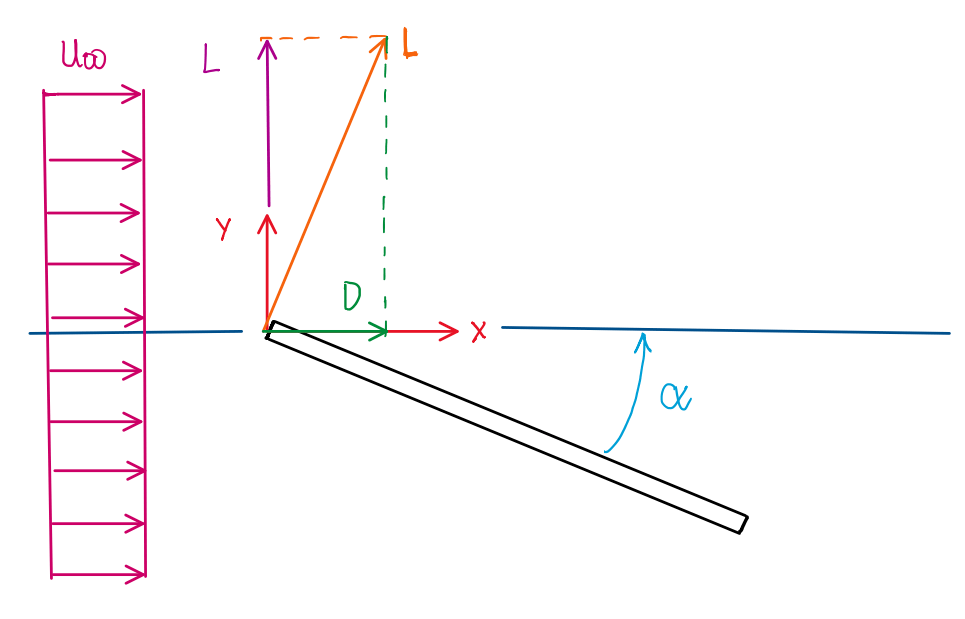
At this point the exercise became a little bit complex, the flat plate is rotated about z axis. The angle of attack produced is α = – 0.1 rad in order to generate a lift L = 180 N. In addition, the flat plate is assumed to behave as elliptical wing. The questions are to calculate the induced (4) and the form drag (5). To understand how to arrive at these angles it is important to know the basic angles of wing, as illustrated at Figure.
Question 4

As can be seen, the are drag components, one due to the induced angle of attack and the other, due to the drag generated by body shape. The first step is to use the informations that question already have, α and L, thus it is possible to write the equations for total induced angle of attack and lift, repectively.
L = CL∙q∞∙S → CL = L/(q∞∙S) = 180 /[960∙(1∙0.75)] = 0.250
αi = CL/(π∙AR) = 0.250/[π∙(1/0.75)] = 0.059683104 ≃ 0.060 rad
Di = L ∙ Tg(αi) = 180∙Tg(0.060 rad) = 10.75573259 N = 10.756 N
As can be seen at Figure 1 and by the calculations, the induced drag component is very small. It is quite clear that the forces produced due to airflow can be calculated by trigonometric relation in the rectangle triangle.
Question 5
The same process can be applied to the form drag, which is more easy to calculate since α is already known.
cos(α) = L/Lƒ ; sin(α) = D/Lƒ
Tg(α) = sin(α)/cos(α) = (D/L)/(L/L) = D/L → D = L∙Tg(α)
D = 180∙Tg(- 0.1) = – 18.06024098 N = – 18.060 N
Third section

The third section of calculations is about the total angle variation of α = – π/2 rad, but with a drag resistance of CD = 1.3 and a pressure coefficient of Cp,b = – 1.1, The calculation requested is the average Cp,f, which is the frontal pressure coefficient (6) and the energy content generated per unit of length x (7).
Question 6
According to Figure 3, it is possible to understand the situation. When the flat plate is rotate until – π/2 rad the drag coefficient is the sum of the average values of the pressure coefficient at the base and the front of the plate. The development of this is based in:
D = – q∞∫cp n dS → D = – q∞∙cp ∫n∙i dS
Since the definition of expression of pressure coefficient CP is:
Cp ≡ (p – p∞)/q∞ → Cp∙q∞ = (p – p∞) → Cp∙q∞ = p
This can be applied in the drag definition, which is straigthforward written due to the actual position of the plate:
D = q∞∙CD∙S = q∞∙CD∙(b∙c)
With these last 2 equations, it is possible to substitute them into the drag integral due to the pressure coefficient:
D = – q∞∙cp ∫n∙i dS → D = – p∫n∙i dS = – q∞∙cp,f ∫n∙i dS
The expression for the pressure coefficient at the front face of the plate is described above. Since the drag is the difference of the pressure at front and base faces, it is possible to write:
D = – q∞∙cp,f ∫n∙i dS – q∞∙cp,bf ∫n∙i dS
Since the drag definition is D = q∞∙CD∙S, it is possible to write:
q∞∙CD∙S = – q∞∙cp,f ∫n∙i dS – q∞∙cp,b ∫n∙i dS
Developing the integral it is possible obtain the product between the vectors n and i, which the outward normal and the displacement vector at x direction. This product have different results since n vector of each face of the plate point to opposite direction, thus:
q∞∙CD∙S = q∞∙cp,f ∙S – q∞∙cp,b∙S
CD = Cp,f – Cp,b → Cp,f = CD + Cp,b = 1.3 + (-1.1) = 0.2
Question 7
The last question ask about the energy content in a wake per unit of length x, this is given by E0‘. However, this is basically the drag due to pressure over the surface, thus:
D = q∞∙CD∙S = E0‘ → E0‘ = q∞∙CD∙S
E0′ = 960∙1.3∙(1∙0.75) = 936 N
References
- Stalio, Enrico. Aerodynamics. October, 2021;
