The beginning of the computational fluid dynamics CFD analysis is called pre-processing, it is defined by the CAD model definition and the mesh surface. In this stage, the turbulent equation (RANS equations) are set for all elements on the model surface and the environment. The Navier-Stokes equations are defined for the discretized model. After that, the boundary conditions are defined and the simulation is ready to initiate. Neither of this process is performed manually, except the splitting of the CAD model in parts is an example. Processes relative to the mesh, as surface mesh and morphing are automatic. However, a well done split is required to define the best parts of the car to be analyzed, for instance, the side pod blanks, wheels and diffusers.
The watertight model
Although the CAD model is important for a CFD analysis, the watertight model (WM) is a key point for it. Actually, this is a version of the CAD model, but including only what is really important for an aerodynamic CFD analysis. Hence, some parts could have its features more simpler to reduce the computational effort. Through WM it is also adjusted to the mechanical set of the car in the CFD simulation. In other words, ride height, camber, tire deformation, toe and wings configuration.
The main inclusions of the watertight model for CFD runs are wheels, cooling ducts for radiators and intercoolers, brake ducts, under-hood ducts and diffusers. For each one there is a reason for their analysis. For instance, ducts for cooling, in any system, are usually analyzed in terms of the amount of mass flow through, if this is enough or not, if there is the amount of energy required to maintain the engine in its operating temperature or if brakes are properly cooled.
Wheels
Wheels are very complex parts of race car aerodynamics. Since tires are components sensitive to wheel loads (FZ), they are transient. This means that their effects are always changing. In addition, tire rotation generates a wake which disturbs the airflow through the wings. The CFD analysis on wheels is focused on the consequences of the tire rotation. There are three points of analysis, the upper, lower and inner part of the wheel. The first accounts the wake generated, thus the drag. This occurs due to the detachment point of the flow, which is at the upper part of the tire. The width and the shape of the wake can result in a severe drag increase.
The lower portion of the tire is as critical as the upper one, because of the contact patch deformation, the camber and the toe angles. Usually, race cars run with a lower pressure and negative camber. In other words, an unsymmetrical contact patch. The result is the squishing of the air in that region. This disturbs the airflow to the underwing of the car, thus the downforce generated at that region. In other words, the tire distortion can induce a flow separation on the inner region of the bodywork [2]. The internal part of the wheel is accounted for in CFD analysis due to the presence of the brake disc. Usually, a duct is used for cooling. This region is important because the amount of cooling at that zone defines the tire and the brake temperatures. Hence, that duct is used for rim and brake disc cooling. The CFD analysis at that point indicates the blockage effect and how much mass airflow is provided to these components.
Domain boundaries
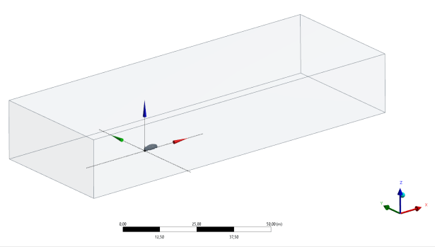
The environment in which the CFD analysis is done is well defined, a rectangular volume with the watertight model inside of it. However, this one is cut longitudinally in two halves. Hence, the simulation is run at just one-half of the car. The rectangular environment is a 50.0 x 20.0 x 20.0 m structure in which the car is positioned in order that the distance between the leading edge and the front axle is 20.0 m; thus, from this one until the trailing edge is 30.0 m. The reason behind this volume is that race cars usually leave behind a great wake. This must be evaluated by the aerodynamicist to understand the effects of the wake on the car behind. An important feature of the environment is the effect of the ride height. Understanding that the car changes it at any driving condition, it is possible to rotate the environment according to this. For instance, considering the difference between rear and front ride height due to the static setup, rolling and pitching. This feature is very useful in oval racing where the corners have a great banking.
On road cars, the computational domain, the rectangular environment, is different in terms of dimensions. In this case, it is 120 x 20 x 44 m since the objective is to reproduce the boundary conditions of open roads. Additionally, it is possible to add some ground boundary layer to mimic the wind tunnel in which the car is under evaluation.
Ride height effect and aeromaps
For top class racing cars, one of the main parameters for a good aerodynamic performance is the vehicle ride height. Once modern race cars have good data acquisition systems, the most representative ride height (RH) can be segregated to be used in CFD simulations. Actually, race cars are usually developed in terms of aerodynamics in two environments, wind tunnels and CFD simulations and RH data allow building a sensitivity analysis of the main car movements, which are yaw, roll and steer, relative to RH. The car should be in a domain that is in the map point requested to simulate. There are different phases of the car at the track, these are straight line acceleration, braking, high speed and low speed cornering. All of them have a range of RH inside the map point. Although it is too time consuming to simulate all map points, it is possible to extract some sampling points of each condition in order to obtain the car sensitivity to RH. The same kind of procedure done at the track is also performed at the wind tunnel and CFD simulations. Actually, the data collected at the track will be used to feed those processes. The first analysis is the baseline one. The results do not reach the target, which is more or less expected. Hence, the development is started by changing surfaces in different areas in a tentative approach to clean the flow, to low the drag, to increase the downforce and to stabilize the car balance. However, all this work is useless if the car is only evaluated in a single condition, because this loses the behavior of the option during the real track test. For instance, when the ride height is being modified and this car goes around a corner, RH will change. The impact is that some options are good for some situations, but bad in other ones.
Morphing
Hence, typically the development is done in two ranges of map points, checking different car configurations in terms of RH, roll and steer. In a CFD environment this is done by a static model. This one is frozen at the desired RH, then the simulation is started. Each simulation with different RH requires to return to the CAD model and modify the geometry, because the RH variation impacts on the wheel camber and suspension layout. However, this process is too time-consuming and requires a better approach. The trick to avoid this is called morphing. The automation in this case is to have a design RH which is morphed, in other words, freezing the suspension and rotating the wheel according to the camber value to automatically change RH of the simulation. The advantage of this method is that it does not require going back to the CAD design, the list of RH that should be simulated is already defined. Hence, the CFD process will perform only the defined RH. Algorithms do the process of moving the domain, morphing the suspension and arranging these movements to achieve a specific map point. The map points are really pure geometrical, mechanical, and 3D movements that can be analytically written. However, this process is not done for each condition. For instance, in a straight-line condition, it is accepted that the contact patch is approximately the same. At high- and low-speed cornering movement, this assumption can not be made. Morphing processes are done on the body, the surfaces are adapted and the wheels are changed in order to put one sample point and then change to another sample. All this process delivers the position of the car relative to the domain as a basic preparation; in other words, the watertight and the huge CAD with all the wheels. There are other kinds of simplifications to make the CAD workable on CFD, but more important is how the mesh is discretized.
References
- This article was based in all notes made during the Industrial Aerodynamic lectures attended in Dallara Academy;
- Newey, A. How to build a car. Ed. 5, London: Harper Collins Publishers, 2017, ISBN: 978-0-00-819680-6.
