
This exercise proposes a series of calculations over an elliptical wing, this is exposed to flow field with U∞ = 100 m/s and ρ = 1.2 kg/m³ and the wing exhibits an induced angle of attack of α = 0.1 rad. The features of this elliptical wing is that the chord b = 8 m, the aspect ratio AR = 6, the lift slope a0 = 2π rad-1, the no lift angle α0 = – 0.02 rad. In addition, the geometrical and the dynamic twist are null, thus the angle of attack and the no lift angle are not functions of the span wise, thus α ≠ ƒ(y) and αL=0 ≠ ƒ(y).
First part
The first part of this exercise proposes an elliptical wing under α variation.
Question 1 – Calculate the lift slope
Since this wing has an elliptical distribution, its lift and circulation is also elliptic. Another important detail is the twist, both geometric and aerodynamic one are zero. This implies that CL = cL, the global and the local lift coefficient are equal, and the lift slope is independent of y. Therefore, the slope of the lift line can be calculated by:
a = a0 / [1 + a0/(π*AR)] = 2π/(1 + 2π/6π) = 2π/(1 + 1/3) = 2π/(4/3) = 3π/2
Question 2 – Calculate the effective induced angle αeff
Understanding that the induced angle of attack in an elliptical wing at null lift is α0 = – 0.02 rad, it is possible to calculate αeff. However, previous to perform this calculation, it is important to understand the wing behavior.
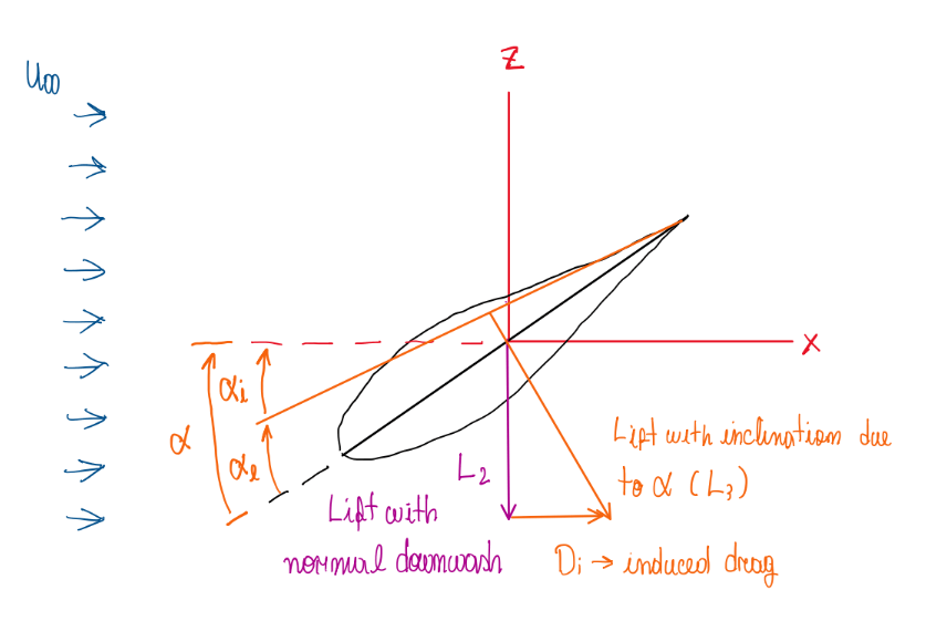
As can be seen on Figure 1, there is lift component orthogonal to the wind free stream velocity U∞, this is clear from induced effects and is given by L2, a vectorial lift for a three dimensional wing in the direction orthogonal to the apparent wind L3, which is also called effective wind. This is at an angle αeff respective to the wing, which is the effective angle of attack. Hence:
α = αi + αeff
CL = cL → cL = a0∙(αeff – αL=0) = a∙(αeff – αL=0) = (3π/2)(0.1 + 0.02) = (3π/2)×0.12 = 0.565
αi = CL/(AR∙π) = 0.565/6π = 0.03 rad
α = αi + αeff → 0.1 = 0.03 + αeff → αeff = 0.1 – 0.03 = 0.7 rad
Since the elliptic wing of this case has no geometric twist, the induced angle of attack and the zero lift angle are not function of y. Hence it is possible to assume CL = cL and simplify cL = a∙(α – αi – αL=0). This occurs, because cL equals zero when α = α0.
Question 3 – Calculate the downwash applying all the usual trigonometric approximation
This question requests the calculation of the downwash component, which is the vertical component generated between the velocity vector U and Ua as illustrated at Figure:

An important detail about the downwash is its constant value along the wing span, but only in cases of elliptical circulation distribution, or elliptical wing. Hence, applying the geometrical approximation:
sin(αi) = ω/Ua ; cos(αi) = U∞/Ua → Tg(αi) = sin(αi)/cos(αi) = (ω/Ua)/(U∞/Ua) = ω/U∞ → ω = U∞∙Tg(αi)
ω = U∞∙Tg(αi) = 100∙Tg0.03 = – 3 m/s
Question 4 – Calculate the circulation respective to the center of the wing, y = 0 and justify the application of the formula ω = – Γb/2b
Considering the circulation at the center of wing results in a downwash of ω = – Γb/2b. Actually the downwash is a negative velocity vector that changes along the wing span. Hence:
ω = – Γb/2b → Γ(y) = Γ0√[1 – (2y/b)²] → Γ(y=0) = Γ0√[1 – (2∙0/b)²] = Γ0
Γ(y=0) = Γ0 → ω = – Γ0/2b → Γ0 = – 2b∙ω = – 2∙8∙(-3) = 48 m/s²
This procedure describes that at the middle of an elliptic wing, the bound vorticity is maximum at this position. In addition, the downwash is not a function of the wing span position, y. Hence, ω = – Γb/2b can be applied due to the assumptions for elliptical wings, which are the elliptical distribution, αi ≠ αi(y), α0 ≠ α0(y) and ω ≠ ω(y).
Second part
The next section of this exercise is the variation of the induced angle of attack to αi = π/10 rad, thus the velocity profile at ξ1 coordinate from the leading edge is given by:
(U(ξ1)/U∞) = 4η4 – 11η³ + 9η² – η ; η = η*/δ(ξ)
Where ξ is a parallel and curvilinear coordinate of the wing profile, η is the coordinate at normal direction respective to the wing profile. It is a non-dimensional parameter since η* and δ(ξ) are dimensional.

(U(ξ1)/U∞) = 4(η*/δ(ξ))4 – 11(η*/δ(ξ))³ + 9(η*/δ(ξ))² – η*/δ(ξ)
Question 5 – Verify if the flow separates
In this kind of question, the velocity profile equation is used to verify the pressure gradient near the wing surface. Hence, the variables will be (ξ1, η = 0). The condition for separation is the velocity gradient tending to zero at the wall, thus (∂u/∂η*) = 0 when η* = 0. Hence:
(U(ξ1)/U∞) = 4(η*/δ(ξ))4 – 11(η*/δ(ξ))³ + 9(η*/δ(ξ))² – η*/δ(ξ)
∂u/∂η* = U∞∙[4(η*/δ(ξ))4 – 11(η*/δ(ξ))³ + 9(η*/δ(ξ))² – η*/δ(ξ)]
∂u/∂η* = U∞∙[4∙4(η*/δ(ξ))3 – 3∙11(η*/δ(ξ))² + 2∙9(η*/δ(ξ)) – 1/δ(ξ)] ; η* = 0
∂u/∂η* = – U∞/δ(ξ)
As can be seen, ∂u/∂η* is negative. The separation occurs when ∂u/∂η* = 0, but there is another condition for separation, which is the adverse pressure gradient.
∂²u/∂η*² = U∞∙[3∙4∙4(η*/δ(ξ)4)2 – 2∙3∙11(η*/δ(ξ)³) + 2∙9(1/δ(ξ)²)]
∂²u/∂η*² = U∞∙[3∙4∙4(η*/δ(ξ))2 – 2∙3∙11(η*/δ(ξ)) + 2∙9(1/δ(ξ)²] ; η* = 0
∂²u/∂η*² = 18U∞/δ(ξ)²
However, the second partial derivative is also equal to:
∂²u/∂η*² = μ-1(dP/dξ1)|η* ≈ μ-1(dP/dξ1)
18U∞/δ(ξ)² = μ-1(dP/dξ1)
(dP/dξ1) = 18(μU∞/δ(ξ)²)
It is possible to notice that occurs separation, but the velocity gradient is negative at the wall.
Question 6 – Verify if the pressure gradient is adverse
u(du/dx) = -ρ-1(dp/dx) → u(du/dξ1) = -ρ-1∙18(μU∞/δ(ξ)²) = -18(υU∞/δ(ξ)²)
du/dξ1 = -18(υU∞/Uδ(ξ)²)
Therefore, since du/dξ1 is negative, the pressure gradient has the conditions to be considered adverse, which are dP/dξ1 > 0 and du(ξ1)/dξ1 < 0.
Question 7 – Calculate the pressure gradient at (ξ1, η = 0)
(dP/dξ1) = 18(μU∞/δ(ξ)²) = 18∙18∙10-6∙100/δ(ξ)² = 0.0324/δ(ξ)²
Conclusion
The first part of the question deals with variation of the aerodynamic forces when the wing changes its angle of attack α. It is important to understand that when α changes, force components arise due to two angles, αeff and αi, which are the effective and the induced attack angles. The first is respective to the effective airflow. Although most of these kind of questions assume uniform flow, there is this “resultant” airflow over the wing. Its lift component is orthogonal to the effective airflow line. Hence its angle with the lift respective to the free stream coordinate is the proper αi. Another interesting point is that these lift component must no be confused with the resultant lift at the wing structure. The second part of the exercise is interested on the flow characteristics, basically what leads the flow to separates from the wing surface. Once the velocity profile equation is given, it is straightforward to find the flow characteristics that defines the flow as prone to separate or attached. Basically, when the pressure gradient is positive (dp/dx > 0) and the velocity gradient is zero (∂u/∂y), the flow separates from the wing surface.
