Composite materials request many standards in order to test them with an adequate reproducibility and repeatability. However, since they are made from different compounds, they have a quite wide range in their characteristics and properties with respect to metals. These change according to two aspects, the process and the layup. For instance, parts made from metal by casting and machining exhibit some common properties. On the opposite, components made by compression molding, RTM or autoclave exhibit significantly different properties. If they are solely made by one of those manufacturing processes, but with a different layup, then they are completely different materials and components. Hence, the testing procedures and standards are important to determine the material behaviour and clarify any hidden material characteristic.
Test Plan
Since composite materials are complex, the testing procedures and their output are also difficult to plan. Actually, these are based on the desired length scale. This for composite materials, are five, the structure, the laminate, the lamina, the constituent and the microscale. Ideally, all those scales should be considered, but this amount is limited by two important factors, cost and results. Which normally are very well defined in the beginning of the design process. Hence, the approach of the Building Block is adopted. Its objective is to define the level of the test and the desired results. Actually, neither all test levels are standardized, the ones that go deeper into the material properties are more experimental. For instance, an example of a test at the structural scale is the aircraft wings. It requires a big rig and a site only dedicated to that. In addition, it is possible to visualize the wing deformation, which usually is a characteristic of a test at the structural level. In racing car design, the composite materials are tested focusing on the impact absorption. Hence, properties such as strength and stiffness have more attention. The classical lamination theory (CLT) is used to predict the material behavior, which with respect to a monocoque is its impact attenuation.
Since neither all cases have a proper standard test, the scale of the testing plan is defined according to the situation. Usually, in racing car design, tests are performed at the laminate level, because the delamination is a problem that occurs at this one. Since the complexity of a composite material is high, the test is usually performed on a single ply from an unidirectional laminate. Then the test result is multiplied by the amount of plies. Another important aspect that defined the level of the test is the manufacturing process. For instance, prepreg tape layering, resin transfer molding (RTM), compression molding and thermoforming are tested at the ply level, while the filament winding and pultrusion are tested at the laminate level.
Test Representativity
Tests must be representative for an entire batch, then there is a proper amount of experiments to provide a robust average and standard deviation. Usually, about 5-6 tests are the minimum to have trustful results. Another very important detail regarding the test representation, is the amount of specimen batches. The specimens are made from composite materials, thus fibers and matrix. Each one of these have their own average and standard deviation, thus they can have a significant impact on the levels if only one batch is considered. For this reason, it is taken for evaluation 5 different batches of fibers and matrix. Then, the average and the standard deviation of these compounds are spread in order to account for the best fiber and matrix properties of all batches. Actually, this does not make the specimen properties repeatable, but they will vary inside a controlled range of the material properties.
Test Category
The test category is defined with respect to the aspects that will be evaluated. They can be physical or mechanical aspects. The first one evaluates properties like density, glass transition temperature Tg, thermal expansion, ply thickness, the resin and fiber content and the specific heat. Regarding the mechanical properties, it is evaluated the tension, the compression, the bending, the in-plane tensile shear, the rail shear, the in-plane interlaminar and transverse shear, the double cantilever beam, the end notch flexure and the mixed mode bending. The last three types are performed to determine the delamination, but they also combine different loadings. The objective is also to verify the opening modes, which is one of the modes that a fracture can propagate. The bending test is useful to evaluate the flexural behavior of the material.
Tension test
The tension test is based on D3039 and D3479, this one evaluates fatigue and D3039 provides a static analysis. However, both uses the same kind of specimen, an epoxy plate with tabs bonded at the extremities. Since those standards are from ASTM, the measure of the plates are given in the Imperial system of units. Hence, the specimens are 0.5” and 1” width. The difference between them, besides the width, is the amount of plies and the test orientation. The specimen with 0.5” has 6 plies and the test orientation is 0°, while the 1” specimen has 8 plies and is evaluated at 90°. The specimen has a free length of 6”, which is the distance that separates the two tabs. These are important to improve the grip of the test machines fixtures on the specimen.
The tabs are usually made from E-glass epoxy or aluminum. Actually, that depends on the kind of composite that is being tested. Usually, tabs are made from a material that do not have a too high Young’s modulus. In composites with these parameters varying between 30,000 and 50,000 MPa, an epoxy tab is enough. If the composite is stronger than that, the aluminum tab should be used. This is quite important, because at the region where there is the transition between the composite plate and the tab, it is natural that some stress concentration is developed. However, if the imbalance between the plate and tab strength is too high, this stress concentration will be enhanced. There are some methods to work out these issues, one of them is by machining a very small chamfer at the transition region. Although this can make this transition smoother, it is a very difficult, expensive and time consuming process since the angle is very small.
Basically, the tension test measures Young’s modulus and Poisson’s ratio. For that, strain-gauges are used to measure the elongation at the longitudinal and transversal directions. Hence, two strain-gauges are necessary. Then, the Poisson’s ratio is basically the ratio between the longitudinal and the transversal deflections. The output of the tension test is given in form of statistics, which is the average of the strength and its standard deviation. The ratio between the average strength and the standard deviation of the strength is called, coefficient of variation. This parameter indicates the degree of repeatability of the experiment. The smaller is the coefficient of variation, higher is the test repeatability. In some tests the results do not exhibit a proper standard distribution. For this reason, the ASTM standards provide power and exponential distributions. This is given by the 2-parameter Weibull distribution. The results are plotted in a graph that correlates the probability of survival and the ultimate stress. This graph suggests that 90° plies have much more variation than the 0° ones. The failure mechanism is too dispersed with respect to the results. In addition, this also suggests that fibers are much more reproducible than a laminate with matrix as one of the components of the laminate.
Compression test
The compression test is based on a specimen with 0.10 x 0.25 x 5.50 inches. Two strain-gauges are positioned on the plate, thus it is possible to measure the longitudinal and transversal elastic modulus and compressive strength. Hence, the Poisson’s ratio can be obtained. There are three standards dedicated to compressive tests, each one has its proper test configuration. The main problem in compression tests is the buckling of the specimen, because it affects the test results. Hence, those kinds of tests vary according to how the specimen is fixed in the machine. In the ASTM D695, the specimen is fixed through screws and has an anti-buckle device. Even though this helps in avoiding buckle, the free area for testing is smaller and this makes the specimen more exposed to failure. In the standards ASTM D6641 and D3410, the specimen is fixed through grip fixtures and axially loaded. The difference is that the applied load is more evenly distributed. In those tests, the region between the grips still is very small in order to avoid buckling.
In-plane shear test
Although the specimens used for the in-plane shear test look very similar to ones from tensile tests, they are different. The fibers of the laminate are displaced in angles and with an amount of four plies. The main objective of the experiment is to measure the in-plane shear stress, which is given by 𝜏12. The shear stress at the principal material direction is assumed as one half of σx. This is the stress at the x-direction. 𝛾12 is the strain with respect to shear and, in this test, is measured by the sum at x and y directions. Then it is possible to obtain the Poisson’s ratio and also the elastic modulus at longitudinal and transverse directions. By those two parameters in the x-direction, the shear modulus is obtained. Another similarity with the tension test is that, in-plane shear test uses the same machine since σx is obtained by tension test. The Poisson’s ratio should be quite similar to the ratio between 𝜏12 and 𝛾12, but assuming the linear condition of the elastic behavior.
Rail Shear Test
The rail shear test is an alternative to the in-plane one in order to obtain a direct measure of the shear at principal material direction. Hence, it is a quite different approach with respect to the in-plane shear. Regarding the specimen, this has a simple shape and laminate, because it is loaded at 90° with respect to fibers. For that, a proper fixture is provided, which is the rail guide. They have a triangular shape, when observing sideways. The fixtures are three in amount and are disposed following the triangular shape. This provides an effect on the load P, that becomes a shear loading in the point of view of the specimen. Then the shear load is P divided by the specimen thickness h. The shear stress is P/h divided by b, which is the length. This direct measure of the shear is only possible due to the hinge effect created by the rails. The only problem of this testing method is that the rail guides are a complex arrangement and make the in-plane test an advisable choice. The measurements of the shear strain is performed on strain-gauge. It measures the strain at 45°, thus it is necessary to multiply by 2 since it measures just one principal strain direction.
In-plane Transverse Shear Test
This is another variation of the shear stress calculation. The specimen and fixture are different with respect to the usual test. The first is a thin plate with a contraction zone. The specimen laminate can have plies in both directions, while the contraction is registered by the use of strain-gauges. Due to its peculiar shape, the specimen is called Losipescus, while the test is sometimes called Losipescus Shear Test. This measures the shear modulus and strength through the application of a force P on the fixture. Actually, this test has a quite different fixture, which fixes the specimen by four supports. These are alternatively positioned in order to transfer the load P equally splitted between those supports. Then, the loading of the specimen is symmetric and the moment generation is also symmetric such that, at the middle of the specimen the moment is zero. To monitor the crash of the specimen, two strain-gauges are used, one at -45° and the other at 45°. The shear stress is calculated by dividing the load P by the cross-section area of the specimen. This test obtains a behavior very similar to the antisymmetric one.
Bending test
Usually, metallic materials have a significant proportionality between the shear modulus G and elastic modulus E. Regarding composites, this is not valid, instead G is used to be quite low with respect to E. The bending test is performed to analyze the flexural behavior of the material and the effects of shear under bending. Since in-plane and out-of-plane elasticity is not proportional in composites, the shear deformability can be neglected. To measure the shear properties, it is assumed a linear behavior up to failure and a slender specimen. This means that, the length is much higher than the thickness. This is the condition to have a negligible shear deformability. Then, the test is performed with several length-to-thickness ratio in order to find the one which provides that condition. The shear deformability is more pronounced in composites than in metals. The usual bending test is based in a three point bending. It is a configuration, which the plate is supported by two supports and loaded at the middle. Since the shear deformability is considered negligible, the failure will occur by bending through the ultimate failure load. Then, the flexural modulus can assume the following form:
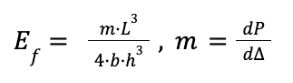
Where m is the load variation with respect to the shear deformability. This approach is only valid for slender beams, because otherwise the shear deflection will affect the test results. Actually, most of them are not perfectly slender beams, thus there is another equation for the shear deformability. This is given by:

The important detail for non-slender beams is that the shear deformability depends on two important ratios. The first is between the Young and the shear modulus (E/G) and the other is the ratio between the thickness and the length of the specimen (h/L). For metals h/L is usually 2.6, thus any ratio below this value is considered negligible. Composite materials used to have low G with respect to E. For G = 5000 GPa, E/G is about 10, thus a very small shear modulus, specially in unidirectional laminates. In woven laminates those ratios are more balanced, then h/L must be higher in order to have a negligible shear deformability. Actually, it is possible to have both cases, thus a slender specimen is allowed. Hence, this test can also be performed using specimens of different lengths. The objective is to evaluate different values of m = (dP/dΔ), which allow to obtain different P and G. Then is obtained the flexural modulus and the out-of-plane shear modulus, which are given by Ef and G, but in this case they become E11 and G13, respectively. However, this is a sort of approximation, because beams under bending exhibit tension in one side and compression in another one. Hence, if there is any difference between these sides, Ef would not be equal to E11. Another important aspect regarding flexural bending, is the volume effect.
This is a correlation between the ultimate failure under tension and the one under bending. In this case, there is a difference in the most requested side, which usually is the outer. This has a negative stress distribution. It is quite straightforward to notice that the zone with a negative stress distribution is bigger than the one with a positive one. If this is compared to a tensile test, the difference is even bigger, because the stress distribution is higher, thus the volume effect is less critical than in bending.
Interlaminar Shear Stress Test (ILSS)
The interlaminar shear stress test is sometimes called shear pin test, because it uses a pin to perform it. This specimen is very short in order to have a L/h ratio that makes the material failure almost exclusively by shear. Actually, there is some amount of bending, but the failure occurs by shear. Usually, uniform laminates are used in order to have a smooth stress distribution. However, if the laminate of the specimen is non-uniform, a 90° ply laminate for instance, the stress distribution exhibits a non-parabolic behavior. Those aspects are favorable in providing the ideal condition for the specimen fails under interlaminar shear. Although this test is quite simple and the pin is easy to manufacture, it tends to fail near to its supports. This reduces the precision of the results, which is the reason why it is not frequently adopted.
References
- Jenkins, C.H. Manual on Experimental Methods for Mechanical Testing of Composites. Edition 2, Society of Experimental Mechanics (SEM), 1998.
