It is important to understand how stress behave inside the bonding connection. Since there are several configurations, each of them must be analyzed in order to select the correct one according to the requirements. The main joints are the single-lap, the double-lap, the scarf/bevelled, the doubler, the cylindrical, the butt and the peel ones.
Single-lap joint

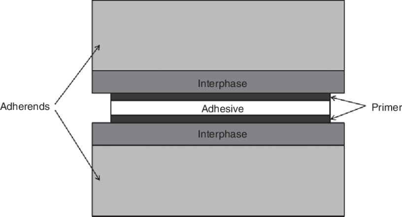
The single-lap joint is also called, overlap one. It considers two types of adherents, the rigid and the flexible ones. In addition, the adhesive and adherents are subdivided into small pieces. Each small square or rectangle is a piece of composite. Considering the case which the adherents are the same, thus the deformation is transmitted rigidly to the adhesive layer. This means that, each point of the adhesive layer is transmitted in the same way. If it is assumed a linear relationship between stress and strains, then if the deformation is constant, the stress is constant. In practice, there is no infinitely rigid adherents. Hence, these are deformed in a non-linear way. Between points A and B, the deformation varies from the maximum value to the minimum one. Indeed, at the point B there is no loading in the x-axis, thus the deformation is zero. On the other adherent, the deformation is exactly anti-symmetrical. Therefore, what actually happens is an uneven deformation which is absorbed by the adhesive layer. In particular, this uneven deformation is maximum at the two extremities of the adhesive layer. This means that, to behave like a linear relationship, then the stress should be maximum at the sides, but zero stress in the middle. For this reason, it is understood that adhesives work better than fasteners, but they do not provide a constant stress across the joint.
Stress concentrations
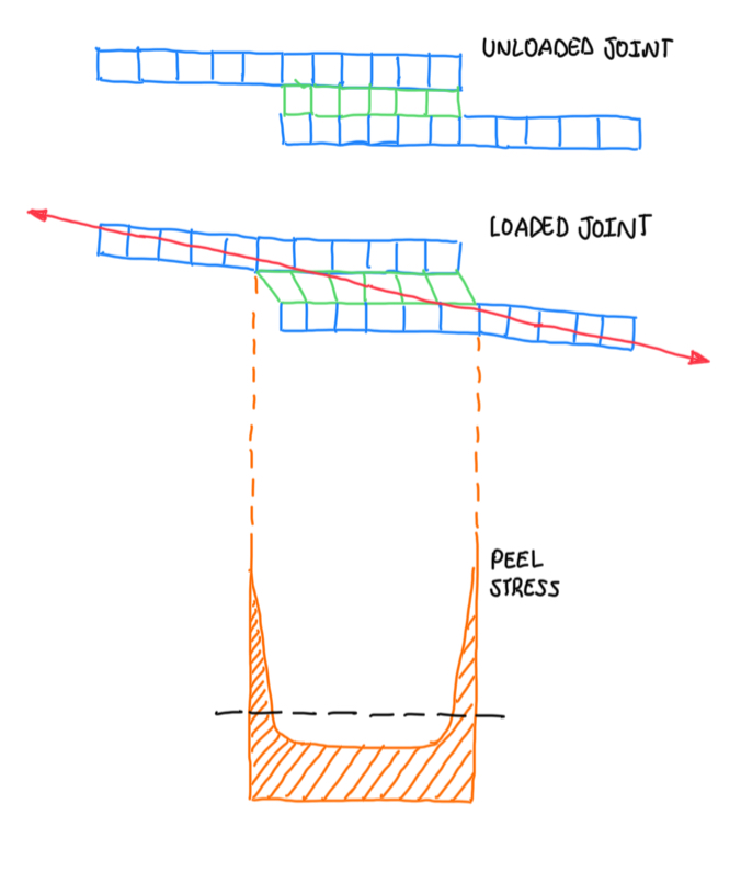
If a joint has some sharp corners, these generates some stress concentrations. The loads pass from one adherent to the other, but there is a difference in height, thus a misalignment. This generates a bending moment over the joint. Hence, when an uneven stress condition is combined with the load misalignment, the corners exposed to the bending moment are also exposed to the stresses. Even though the geometry is normally loaded in shear, it is generated a bending moment that results in peel stresses.
Shear stresses analysis
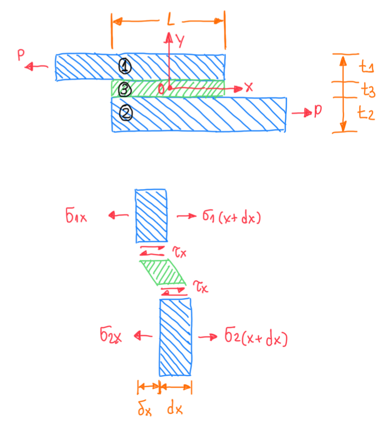
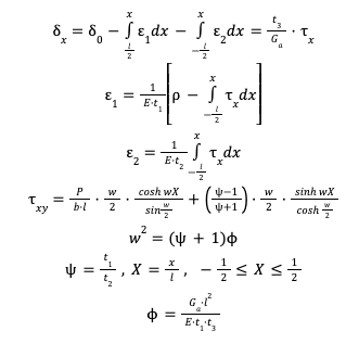
The shear stress analysis is developed by using the shear lag model. This is a closed form solution, which is done by solving a system of equations in order to define the equilibrium of two adherents and the adhesive. Hence, one piece of the joint is under equilibrium regarding the forces P. In addition, ε1 and ε2 are the deformations of the upper and the lower adherents and δx is the displacement between these. In practice, the difference between the axial deformations of the upper and lower adherents is equal to the shear deformation of the adhesive. This is called the shear lag model (Volkersen, 1938), because the adhesive will cover the difference in deformation between the two adherents. The differential system of differential equations has results in a closed form. This is one of the few cases where there is a closed form solution for the stresses in the adhesive layer.
Shear stress distributions for equal adherents
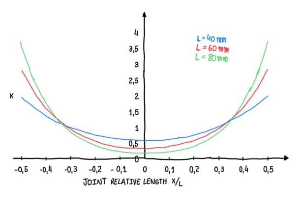
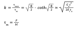
Considering a case of a joint with two equal adherents in which the adhesive inside is an acrylic one. In this situation, it is possible to calculate the ratio τmax/τm, where τm is just the nominal value of the shear stresses. K is a factor that characterizes the stress distribution with respect to the average shear stress. This factor depends on the joint parameters. For this case, there are three different lengths. It is possible to notice that, the lowest value of k is obtained with lower length L. The reason is that K, at the extremes of the joint, increases with the overlap length. Considering 40 and 80 mm overlap cases, these exhibit a K value of 2 and 3.8, respectively. This means that, if the overlap increases by a factor of 2, the average stress decreases by a half and k doubles. Therefore, a big overlap reduces the performance of the adhesive bonding. Nevertheless, this conclusion results in a conflict with one of the adhesive rules, that states to maximize the bonding area. Actually, a very long overlap is not practical, because requires more material and is difficult to operate the adhesive. Therefore, it is enough to have and adhesive with an overlap about to 25-30 mm.
Shear stress distribution for different adherents
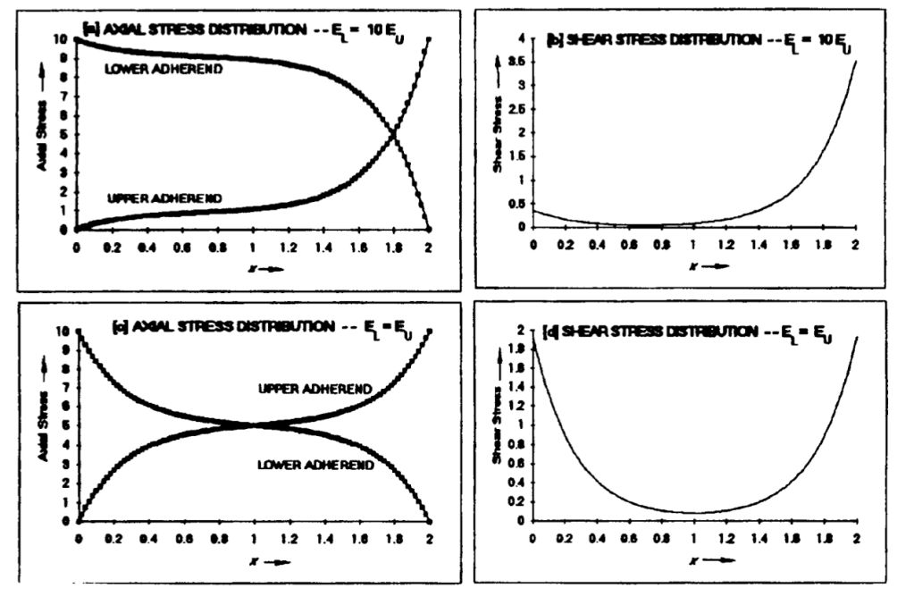
Regarding the case of the shear distribution for different adherents, if the lower adherent is stiffer than the upper one. This results that, the stress distribution is biased to the right side, because the axial deformation of the stiffer adherent is very low. Hence, the difference in deformation between the lower and the upper adherent at the left side will be lower than the right side. Since at the left side, the upper adherent is not deformed, while at the right side it is very much deformed, then the difference in the deformation between upper and lower adherents is minimum and maximum at the left and right sides, respectively. This is a consequence of a biased stress distribution, which results in an unbalanced joint.
Peel stress analysis


The peel stresses also have a closed solution. These are generated by a loading eccentricity and they are given by σy. The parameter m is the ratio of peel stress by the average shear stress. In most of the joints, this value is zero, because this is a shear type joint, thus nominally there are no shear stresses. The stress will only develop at the extremities of the joints. In addition, they are not so negligible. For instance, it is possible to notice an increase of the maximum stress, from 3.5 to 5 times the value of the average shear stress, as a function of the overlap length. Hence, with an overlap joint, it is previewed an uneven shear stress distribution and peel stresses. These must be accounted in order to understand the real failure loading of the joint.
Transverse shear and tension
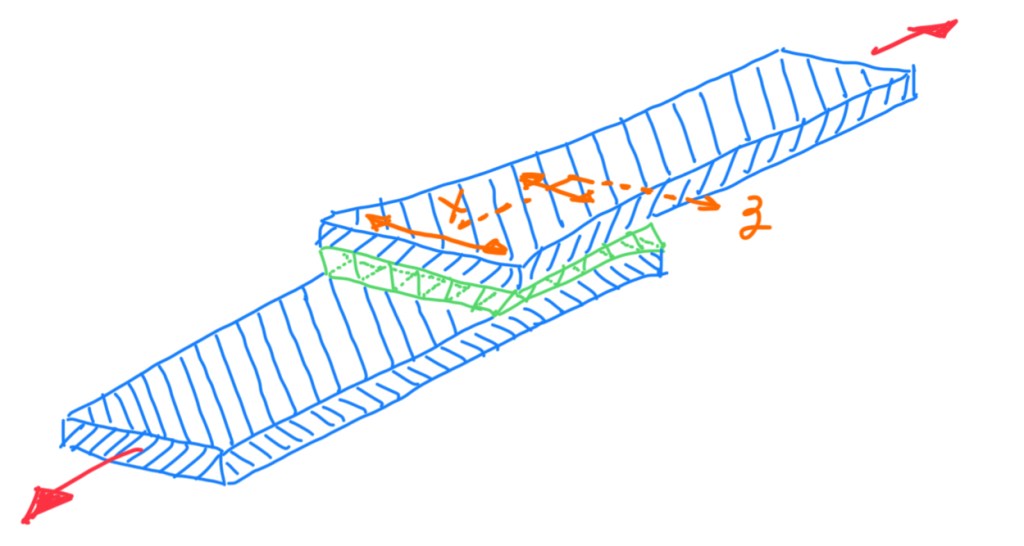
Another kind of component of stress is the one regarding the Poisson’s mismatch. Observing the z-direction, it is possible to notice that the elements are contracting, because the adherents are in tension. Hence, contraction of the lower adherent will be maximum and minimum at the extremes and at the middle, respectively. The reason is that at the center there is no longer load transmitted to the member. Hence, it is possible to notice that, there is both, shear deformation, that occurs transversally, and their variation across the length in x and z directions. This causes compressive stresses transversally to the adhesives layer and shear stress in x-direction. However, in this case, these stresses are orders of magnitude lower than shear stresses.
Strength improvement
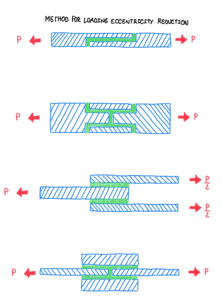
Any modification done in the joint which decreases the difference in the deformation between the upper and lower adherent and loading eccentricity will provide more strength to the joint. There are some solutions for loading eccentricity reduction. Usually, joints are designed in order work in double-shear. This allows to reduce the eccentricity to a half, but it is not completely eliminated. Although the loads are perfectly aligned, their transmission from one adherent to the other still occurs with the flow of forces taking a path which is not straight. This means that, some load eccentricity will occur on the joint.

The solutions for stiffness mismatch reduction exhibit a maximum deformation of the adherent, then the height of the strut is reduced in order to have a similar deformation. Instead to have a high stiffness, this is reduced by tapering the adherent. Basically, the adherents are designed in order to reduce the difference in the stiffness. One of the solutions is reducing the thickness towards the adhesive, by eliminating material. It means that, if there is a sharp edge, the thickness is zero, thus the local stiffness is also zero. The hydrodynamic analogy concept is another solution. It allows to establish similarities between a flow in a pipe. In this case, the flow is driven in changing direction, thus there is less vortex. If occurs a sharp change, then it will be generated more vortex. This means more stress concentrations. That is the reason why different types of joints will perform differently in terms of strength as a function of the adherent thickness.
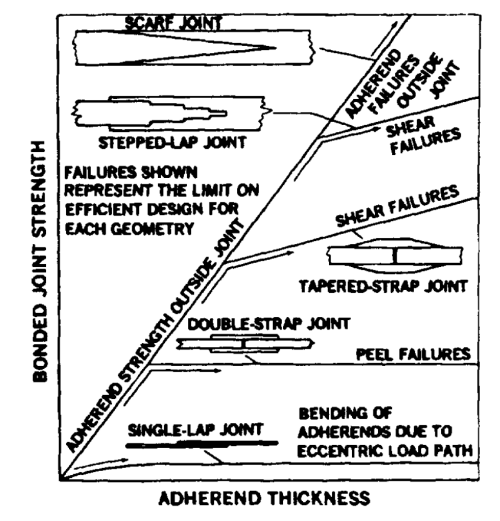
The single-lap joint is the worst solution regarding these aspects. The double-strap one exhibits a better scenario, but with some adherent thickness value, there is no improvement on the strength. The tapered-strap joint has a more linear correlation, thus the thicker the adherents, the higher the loads. Scarf joints are tecnically difficult to be built, but theoretically these give the complete strength of the adherent independently on the thickness. The angle of this type of joint is very small, which means the ratio between height and length is very high.
Another method to enhance the strength of joints is working on the adhesive, which is the tapering or chamfering. In addition, it is possible to notice that strength is further improved when both, the adhesive and adherents, are tapered. Hence, it is possible to have a massive edge of the adhesive. The reason is always the same, because the adhesive is generally softer than the adherent. Hence, there is less deformation mismatch to be compensated. In some cases, the tapering of the adhesive layer may be necessary to avoid local failure, as in the case of metal-CFRP laminate. Independently of the tapering, usually the failure strength value does not vary significantly. The reason is that the mechanism is localized into the composite, similarly to the delamination. In the last case, there is enough adhesive in order to avoid the stress concentration at that region. Then, the delamination will not occur, the failure will occur in the adhesive layer.
References
- Adams, R.D. Comyn, J.W.C. Wake, Structural Adhesive Joints in Engineering. Edition 2, Chapman & Hall, 1997;
- MIL-HDBK-17-3F, Volume 3, Department of Defence (DoD) USA, 2002.
