
In the previous article (read more) it was summarized the testing methods for the mechanical level of composites evaluation. There is another level, which the standards define several tests, that is the laminate one. This evaluates laminates made from filament winding and pultrusion. The main tests are the axial tension, the axial compression, the shear and the torsion ones. This article provides a summary regarding those experiments, their objective and details.
Laminate-level test
The tests explained previously are the ones at the higher level, those are the main shear tests. The test for out-of-plane tensile evaluates a cylindrical specimen pulling it out-of-plane. This kind of test is seldom done, because it requires a quite complex tooling. However, this is the case for the pultrusion of the material which is in the laminate. In filament winding, cylindrical samples can be representative of the laminate, as in a manufacture vessel. For those materials, pultrusion is very often done in profiles like square boxes or plate profiles. Hence, it is possible to test these by pultrusion, bending, compression and shear. In the case of filament winding there is just a circumferential sample, because that shape is typical of that production system. Therefore, there are tests that can be done through axial tension, circumferential tension, axial compression and shear by torsion.
Filament winding testing: Tension

The filament winding testing for tension can be done on samples by axial testing. Figure 1 illustrates the kind of specimen for this test, it is the wall of a hollow cylinder with larger regions at the extremities. This is an approach to have the failure in the free length region at the center. Certainly, it is necessary a sort of expansion fixture devices, which are assembled in the sample in order to expand and put it in the tensile test machine. Another solution is some kind of attachment as a bonded one. In this case, the attempt to be tested it was not found in a cylindrical laminate, because of the bonding relation. If this is sized differently, with a reduced bonding relation, it is a way to test a cylindrical laminate. This tests the filament winding laminate in the axial direction. The filament winding testing for tension evaluates axial Young’s modulus, axial strength and Poisson’s ratio.
Filament winding testing: Hoop
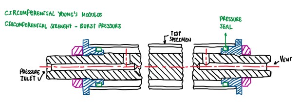
Another kind of filament winding testing is the hoop. This test is usually for vessels in the hoop direction, which is the most stressed one. Hence, this is a type of test that uses a mandrel with an inlet for pressurization of the specimen. This is usually done by hydraulic pressurization, with water or some kind of oil. In this case, it is possible to use a strain-gauge in the hoop deformation. Then the hoop stress is calculated using the theory of pressure vessels. Finally, it can be determined the circumferential Young’s modulus and strength.
Filament winding testing: Compression

It is also possible to test under compression at laminate level. For the case seen in Figure 3, it is possible to determine the compressive Young’s modulus and axial strength. In this case, plates are placed at the extremities, these are done by soft materials. Usually, it is used a polymer. For the example in Figure 3 it is used an epoxy plate. This allows to better distribute the load that come from this self-aligning bearing plate. The use of a soft materials is also recommended to avoid the crash of the structure at the application points.
Filament winding testing: Torsion
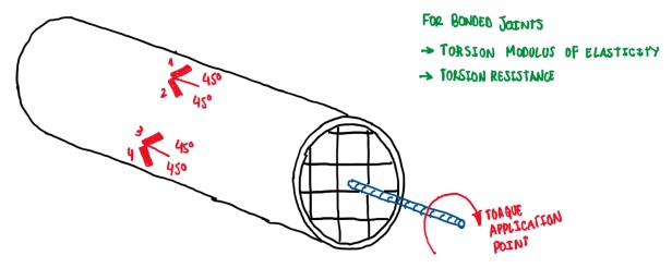
The filament winding tests also have a torsion one, which is not so common. The machine uses cylindrical specimens plugged in the extremities, then it is applied torsion. This test is very useful to verify bonded joints under tension and torsion. Hence, it is possible to estimate the torsion modulus of elasticity and resistance. This last one may vary from the in-plane shear. The specimens are used for complete laminates or sub-laminates.
Sub-element tests

Some tests are performed in complex profiles made from composites and sub-assemblies, these are called sub-element tests. For instance, in the aeronautic field, these tests are done in order to determine the stiffener pull-out force. Figure 5 illustrates an example of a stiffener beneath the skin. The objective is to keep the skim together under the forces acting on the fuselage and the internal pressure. The other types of sub-elements are the joints. The tests are the open hole, bolt bearing and the bolted joint.
Open hole tension test (ASTM D5766)

The open hole test evaluates the notch effect in a specimen. This has a hole in the middle of its free length. Hence, it is tested specimens with different hole sizes in order to determine the characteristics, this is used for design purposes. Actually, this test simulates a region where there is a bolted joint. In addition, there is a hole through the thickness of the composite in order to make the holes clamped together with the two components.
Bolt bearing test

The bolt bearing test is the one performed when there is the necessity to access the load allowed in the case of a bolted connection would loose. This is a situation which the load is no longer transmitted by friction. In general, the bolts are tightened in order to not let them work as an obstacle. Then, the joined parts can transmit the load by friction. However, if the bolt is loose, then there is not enough friction to transmit the load. As a result, the two parts will glide each other, thus the bolt will act as an obstacle. Hence, when there is a load and a fastener, the bolt make a pressure in the hole. This results in deformations that tend to crash the material.

The bolt bearing test (Figures 7 and 8) allows to make several holes in order to perform several tests in just one specimen. In addition, it allows to estimate the load admissible in terms of the deformation of the hole. A small deformation, about 4% of the diameter, is the one corresponding to the bolt bearing load. This is another value required in order to validate a bolted joint. The bolt bearing test determines the load at which there is a residual deformation of the hole, which is 4% of the hole diameter. Hence, the size of the hole in the load direction will expand by 4% of the initial diameter. This is just an admissible value, is not necessarily the fraction.
References
- Jenkins, C.H. Manual on Experimental Methods for Mechanical Testing of Composites. Edition 2, Society of Experimental Mechanics (SEM), 1998.
