
The mechanical characaterization of composite materials have many sources of noise in the data. These can be external agents, problems on the manufacturing of specimens and inadequate environmental conditions. To ensure proper testing procedures, there are several standards that support this process in order to have a precise material characterization. This article provides a summary of the list of standard as well as the details with respect to the very first test, the tensile one.
Standards
The aspects discussed in the previous articles are defined in international standards. These state how those tests must be performed, their conditions, procedures and the specimens, which they also define materials, dimensions and manufacturing. The main standards are listed below:
- ASTM D3039/D3039M-08;
- ASTM D3410/D3410M;
- ASTM D6641/D6641M-01;
- ASTM D695-02a;
- ASTM D790-03.
These are basically variations of tensile, compressive and anti-buckling tests, which will be described in the following topics.
Tensile test – ASTM D3039/D3039M-08
The tensile test is a very basic evaluation when defining the material characterization. It defines the tensile stress in polymer matrix laminates. This test is supported by the D3039/D3039m standard, which describes the procedures, conditions and specimens. Another important aspect of this test regards the material anisotropy, heterogeneity and orthotropy. The laminate is tested at 0°, 90° and 45°, because their orientations are characteristics intrinsic to the material. Usually, the tensile test is performed for materials with high anisotropy. Hence, long fiber composites are usually tested, because short fibers materials exhibit a different behavior, which is more similar to polymer sets. Actually, short fibers polymers can be tested, but specimens with different geometries are required. The results of the tensile test are plotted in a stress-strain curve. Normally, a composite material exhibits a linear behavior until the failure. The elastic modulus at 0° and 90° directions are obtained as well as the shear modulus and the relative maximum stress along these.
Specimen characteristics

The specimens are also defined by standards. Actually, these define the geometry, the acceptable and the non-acceptable failures. Regarding the material and the geometry of the specimen, they vary according to the orientation of the laminate. This can be unidirectional, 90° oriented, unidirectional and symmetric and random discontinuous. Another important aspect defined by standards is the tab. These are components fixed on the specimens in order to provide a good grip of the specimen on the fixtures without damaging the samples.
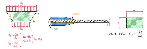
The standards also define intrinsic tab or spacer details, which are the transition length made for a chamfer and the force and the stress that tabs are able to support. Both are defined by an analysis of the stress of distributions at two sections along the transition between the free length and the higher section of the tab. Basically, it is performed to reduce stress concentration by changing the area in which the forces flow. Once the strength of the material (σ) and the shear strength of the adhesive are known, it is possible to calculate the tab length. The chamfer at the tip of the tab is a solution to reduce the stress concentration at the transition.

The dimensions of the specimen vary according to the fiber orientation. For unidirectional laminates, the overall length is 250 mm, the width is 15 mm and thickness is 1 mm. This is a very thin sample, thus it requires a tab, which has 56 mm length and 1.5 mm thick. Hence, the free length is 138 mm. The 90° unidirectional laminate measures 175 mm long and 25 mm wider than 0° unidirectional ones. This case has lower mechanical properties, because the load is being applied orthogonally to the fiber direction. Since the matrix is being loaded, the mechanical properties will be lower. The symmetric-balanced and the random-discontinuous laminates are two specific cases. In addition, there are cases where the specimen is very thick, then it does not require any tab or spacer.
Failures
Basically, there are two types of failures, the non-acceptable and the acceptable ones. The first one does not represent the material characteristics and properties. These usually occur at the tab region due to an incorrect bonding selection or damage inside the laminate. The acceptable failures are characterized by the fact that they occur at the free length of the specimen. However, there are cases where the fracture occurs near the tab. Another characteristic of an acceptable failure is that it occurs through an explosive collapse of the specimen. The ASTM D3039 characterizes both failures through a three letter code, which indicates the failure area, type and location.

There are a lot of different possibilities of failure depending on the position of it. It is possible to have a failure under the tab, a debonding of the tab, at the end of it and at the beginning of the free length or a total delamination of the free length. The first row of failures is characterized by non-acceptable values, because in this case there is damages inside the laminate due to an explicit factor. For instance, considering the failure LIT, if it is observed debonding of the tab, it is possible to suspect from bad sample surface preparation or wrongly chosen adhesive applied to the tabs. Hence, the failure observed is not the one which is interested, the one of the laminate. The second row of failures is characterized by the accepted ones. These usually occurs on the free length, with a shear character that occurs in an explosive way. All these cases can be classified by failure type, area and character, which are described by three letters in sequence. Hence, in a mechanical tensile test, it should be observed not only the recorded values of loads and displacements, but the characteristics of the failure, because this is an important information. The reason is, if any of the failure of first row does not occur, this means that the values of stresses and displacements will not describe the ones of the material. From this point of view, the standards defines the geometry, the type of failure and the method to calculate the elastic modulus.
Geometry

The specimen geometry is pretty simple, it is a rectangular plate that can or not be fitted with tabs. The fiber characteristics adopted are 0°, 90° and 45°. In case of anisotropic laminate specimen, the top-on region of the tab is usually avoided in order to reduce the stress concentration. As a result, the specimen will fail at the region with the smaller section. In the case of Isotropic materials, the top-on tab can be adopted without further problems, but this is valid for metals, not composites.
The geometry of the sample is normally rectangular. In some particular cases of strongly anisotropic material, the top-on geometry should be avoided, because the region of the section reduction due to the top-on shape, its points C and D will have an increased stress concentrations. Hence, it could be expected that, the failure of the material will occur exactly at the point which the section is reduced. On the contrary, top-on geometry could be used for isotropic materials. For instance, it is used for metals because it is strongly different, from the mechanical point of view, of composite materials. Another example are short fibers composite materials on pure polymer samples.
Stress-strain curves
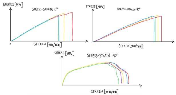
The stress-strain curve for composite materials varies according to the fiber orientations. At 0° and 90° plies, the curves are very similar, both exhibit a brief linear correlation. From this point, fibers adjust themselves according to the loads. After that, there is an increase of the strain in a different slope. Then, the 45° plies exhibit two slopes and a non-linear portion between them. Actually, this case is characterized by shear deformations. Hence, it is possible to confirm that some polymer matrix composite materials and some metals have a plastic behavior of its deformation. In order to create some statistics, the tensile tests are repeated 5-6 times for each fiber orientation. The objective is to build some statistics, curves and properties for the mechanical characterization.
Extensometers
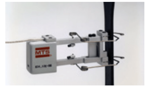
The extensometers are used to measure the strain. Figure 9 illustrates a clip-on axial extensometer under operation, it is placed on the sample surface. Hence, it can be measured the local deformation of the sample. Depending on the gauge length of the extensometer, it is possible to measure different values of the elastic modulus. This also depends on the fact that, with a very small extensometer, as in a strain-gauge applied on the surface, it is measured the strain in a very reduced area of the sample. This means, obtaining a very local deformation of the sample. Hence, for standards measurements, it is usually used 20-25 mm gauge length. This depends on the access available. The 20-25 mm gauge length is sufficiently small to have a local measurement of the strain. Conversely, it is sufficiently large to have a leverage behaviour of the same. Usually, the extensometer information is combined with LVDT transducer one, by dividing the extensometer measurement by its gauge length and LVDT measurement by the free length. Hence, it is possible to have a double check on the two values.
References
- American Society for Testing and Materials. (2008). Standard Test Method for Tensile Properties of Polymer Matrix Composite Materials (ASTM D3039/D3039M-08). ASTM;
- This article is based on the lecture notes written by the author during the Design for Composite Structures of Racing Car lectures at Università di Modena e Reggio Emilia.
