In the motorsport area the differential between a great car and a winning car is their aerodynamic performance. Nowadays this is developed by wind tunnels, that together with computational fluid dynamics (CFD) became the most important tools for a car constructor.
Wind tunnel principles
The basic principle of the wind tunnel (WT) is reciprocity, which means that the flow over a geometry has the same characteristics as a geometry that moves inside the air flow with a given velocity. This is important, because in wind tunnels there is an opposite situation relative to the one at the race track. In this case, the car is moving and the air is at standstill, while in the wind tunnel the air is moving and the car is at standstill. Actually, in the real situation, the wind and the velocity profile is not totally known, but it is reasonable to approximate a situation that the car is running immersed in a standstill air. Another important assumption in wind tunnel testing is the principle of similarity, this means that a point in a given position of the flow will have similar characteristics that other points of the flow field. In addition, the quantities of those characteristics follow a constant ratio. This similarity can be geometric or physical.
- Geometrical similarity: The shape of a test model is equivalent to the shape of the real model and the test model must be placed in a position consistent with the reality.
- Physical similarity: The non-dimensional parameters (Reynolds, Mach and Froude) must be equal to the real problem, along with the turbulence characteristics.
However, wind tunnels are not able to reach the full similarity, because it is practically impossible to reach the physical similarity. Since only geometrical similarity is possible, wind tunnels are qualitatively good to simulate the flow field. In other words, separation, wakes and vortices detachment. The reason of WT limitations is that to replicate Re, Ma and Fr, its structure should be bigger to produce a flow field of the double size, considering that the scale model is 50%.
Re = (ρV∞L)/μ = (V∞L)/υ ; Ma = V∞/a ; Fr = V∞/√g∙l
As a result, not only the wind tunnel facilities should be bigger, as the flow field should suffer from compressibility effects due to high Ma. Fortunately, in the automotive industry, the Ma similarity is not required.
Similarity problem of turbulence
The turbulence intensity is another kind of issue for a wind tunnel similarity, it is given by:
I = u’/U ; u’ = √[(ux‘² + uy‘² + uz‘²)/3] ; U = √[(Ux‘² + Uy‘² + Uz‘²)/3]
The issue of turbulence effects is impossible to replicate perfectly, because there is a certain turbulence intensity inherent to the wind tunnel itself. This not only is different from the vehicle turbulence, as it disturbs the test reproducibility. Usually, wind tunnels have nets and honeycombs panels to reduce this effect. A good wind tunnel operates with turbulent fluctuation about 1%.
Wind tunnel classification
WT are based in two main categories, Ma and its structure, thus the flow regime and topology. Flow regime describes if the wind tunnel operates in a supersonic, hypersonic, compressible or incompressible subsonic regimes. These are defined according to Ma range described below:
- Incompressible, subsonic → (0 < Ma < 0.3)
- Compressible, subsonic → (0.3 < Ma < 0.8)
- Supersonic → (1.2 < Ma < 5)
- Hypersonic → (Ma > 5)
The structure of WT are classified in open and closed loop, this is also called topology. The wind tunnels used in the automotive usually are the subsonic ones.
Open-loop wind tunnels
For this kind of wind tunnels, in order to have a good efficiency of the system, the surrounding volume must be big enough to allow the flow to return from the outlet to the inlet. Hence it is possible to understand that this kind of WT is used with a big atmosphere around it. An interesting point about this layout is that the motor is placed along the diffuser. In this way it must only overcome the loads due to the friction and the pressure loads are lower than the closed loop WT. The main component of wind tunnels are the contraction, the diffuser, the test section and the fan.
Closed-loop wind tunnels
As can be seen on Figure 3, the fan is the only component and part of the wind tunnel that the pressure is positive. All the other parts of WT have pressure drops. Hence, it is possible to write the delta of pressure with all components. After that, the equation is adjusted to deliver the pressure output of the fan. This equation is basically an energy balance for a closed loop WT:
ΔP0testsection + ΔP0diffuser1 + ΔP0corner1 + ΔP0corner2 + ΔP0fan + ΔP0diffuser2 + ΔP0corner3 + ΔP0corner4 + ΔP0HC+grids = 0
ΔP0fan = – (ΔP0testsection + ΔP0diffuser1 + ΔP0corner1 + ΔP0corner2 + ΔP0fan + ΔP0diffuser2 + ΔP0corner3 + ΔP0corner4 + ΔP0HC+grids)
With some manipulations, it is easy to observe that the power of the fan motor is determined by the amount of pressure losses. For this reason it is important to study these losses separately.
Pressure losses in a closed-loop WT
For the diffuser and convergent sections of WT, the pressure losses are proportional to the constant Kfri times the dynamic pressure q∞. This is applied to the Darcy’s equation and is described as following:
ΔP0 = – Kfri ∙ q∞ → Diffuser and convergent sections pressure losses
Kfri = λ ∙ (L/Dh1) = λ ∙ (L/l)
Where λ is the friction factor, L is the duct length, Dh1 is the hydraulic diameter and l is the side length of the duct (square). It is important to notice that the second form of Kfri is only applied if the wind tunnel test section has a square section. The friction can be estimated by L and l. In addition, the divergent and convergent ducts have differences in the total pressure. The diffuser duct has a higher pressure drop, because the velocity is too low that induces an adverse pressure gradient. This effect is also valid for square ducts. For the other sections of WT, the losses are summarized below.
ΔP0corner = – Kcorner ∙ q∞
ΔP0rad = – Krad ∙ q∞
ΔP0screen = – Kscreen ∙ q∞
ΔP0honeycomb = – Khoneycomb ∙ q∞
The corner, radiators and screen sections also induce pressure losses, these are expressed in terms of a constant K given for each case. The common values for these are between 0.15 and 0.20 for corner sections with turning vanes, 2 and 4 for radiator section, 0.5 and 1.0 for screen section and 0.1 for the section with the honeycomb screen.
Figure 4 illustrates a schematic of the test section as a control volume. For this, the calculation procedure is not anymore performed as a function of a constant. Usually the momentum balance is applied on the test section. Basically, the momentum balance, or the motion quantity, is equal to the forces acting on the volume. In this case it must be considered the drag on the car and the pressure forces due to the flow. If the inlet and the outlet of the test section area are equal, this contribution will be equal to zero. Hence, it is possible to infer that p1∙A1 – p2∙A2 is equal to the drag D of the car times the constant Kobst, which is a correction factor due to the obstruction of the flow by the car body. The reason behind this constant is due to the fact that WT tests different models, thus this constant depends on the model type under test. Hence, the momentum balance can be described below:
ρv2²A2 – ρv1²A1 = -D∙Kobst + p1∙A1 – p2∙A2 → 0 = -D∙Kobst + p1∙A1 – p2∙A2 → D∙Kobst = p1∙A1 – p2∙A2 → ΔP = -(D∙Kobst)/A
D = q∞∙Cx∙A∙SF² → ΔP = -(q∞∙Cx∙S∙SF²∙Kobst)/A
Where SF is the model scale factor (for 50%, SF = 0.5) and Kobst is the correction coefficient due to the presence of the obstacle (typically between 1 and 2.5). The delta pressure is equal to the expression with the drag times the correction coefficient. This is the constant K due to the model, Kmod and together with the coefficient due to the presence of the wall, Kfri, these result in the model coefficient inside the test section.
Kmod = D/(Aρv²) = (Cx∙S∙SF²∙Kobst)/A;
Kfri = λ ∙ (L/Dh1) = λ ∙ (L/l)
Ktot = Kmod + Kfri
ΔPts = – Ktot ∙ q∞
Finally, the total pressure loss inside the test section is equal to the negative product of the total loss coefficient and the dynamic pressure, as described above. The reason behind the negative sign is due to the presence of a loss. It must not be confused with the delta pressure sign. The car is a kind of an obstacle, thus Kmod depends on the type of the car. The point is that the pressure record must not be confused with the loss one. They are related, but different, because the contribution of each section of the wind tunnel (WT) is what really matters. The fan power estimation is related to the mass airflow through the duct and the pressure jump after the fan. This must overcome all the pressure losses on WT. In addition, this equation is important to verify how much is the velocity which is possible to achieve on the wind tunnel, because all these losses are proportional to wind field by the term of the dynamic pressure. This accounts for the squared value of the velocity. Hence, given the power of the fan, if there is a too high wind tunnel speed, this is probably the fact that at a certain point these losses are higher than the power of the fan. Therefore, this equation is important to verify the maximum speed of the wind into the loop, given the power which the fan is able to produce. This speed refers to the speed inside the test section.
Main components of wind tunnels for race car applications
Since WT used for race cars development are the closed loop ones, from this section onward, these may be approached as wind tunnels. The main components in closed-loop WT are the fan, the deflector fins, the heat exchanger, the turbulence damping section, the contraction, the test section and the diffuser.
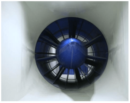
Fan section
The main component is the fan since it creates the flow field inside the loop. It is placed on the opposite side of the test section, because the pressure losses at that point are minimum, thus the power request on the motor is lower. In addition, this configuration minimizes the turbulence effects created by the fan. The pressure loss induced by the fan is lower if this is mounted in a region of low speed of WT. Hence, the diffuser is used to slow down the velocity of the wind, which reaches the fan at low speed. Since there is a diffuser before the fan, the difference before and after will be lower, then a lower power will be required for the fan.
Deflector fins
The deflector fins are located in the curves of WT, they are introduced in order to reduce the losses due to the presence of the curve. Considering that the expression of the pressure drop depends on the dynamic pressure q∞, there is the coefficient K, which is the drop coefficient. This is used to evaluate the efficiency of the vanes. Actually, with no vane, the pressure drop is q∞, while with the deflect fins, K oscillates between 0.15 and 0.20. Hence, it drastically decreases with the vanes.
Heat exchangers
Even though there is not significant heat generation inside WT, in some applications heat exchanger is included. The main reason is the fan, it heats the air due to its great power. In addition, there is the friction due to the boundary layer, which results in temperature variation, and the radiation of the environment results in some heat transfer to the air flow. The importance of the temperature control is to not cause a great variation of the air density ρ (kg/m³). For instance, a temperature increase of 10 °C results in a density reduction that leads to a variation of the aerodynamic forces over the wind tunnel model. As a support, some wind tunnels use settling chambers to have more control over the flow temperature after the big diffuser. This provides more stability in the air flow temperature.
Turbulence damping section
The turbulence damping section is introduced to keep turbulence intensity (I) on WT as low as possible, thus nets and honeycomb panels are used. Nets reduce the velocity fluctuation in the flow direction, while the honeycomb panels are used to reduce the orthogonal components of the fluctuation. These components are placed in cascades and progressively reduce the permeability of the air flow direction. Consequently, turbulence is progressively reduced inside WT. Turbulence is usually measured in order to verify if it is inside the tolerances.
Contraction section
The contraction section is displaced after the honeycomb and immediately before the test section. The reason is to accelerate the flow directly to the test section without increasing the fan power. It uses a contraction area in order to increase the velocity of the flow previously to the test section. The usual area ratio (Ain/Aout) is between 5 and 9 which means that the velocity is increased by this ratio while the pressure losses are proportional to the square of the velocity. Typical contraction sections have Ain/Aout ratios varying between 5 and 9 and semi-angles α/2 about 12°
Test section
The test section sometimes defines the kind of wind tunnel, because its section shape, which can be circular and squared. The first is mostly used for aeronautical applications, while the squared test section is used for automotive applications. The reason is, because in ground vehicles, the surface movement needs to be accounted for. This test area must be large enough to accommodate the wind tunnel model (WTM) and does not generate blockage effects due to the wall. Basically, for WT sections if it is used only a certain type of WTM, these usually vary in terms of scale, that is between 40% and 60%.
Diffuser section
The diffuser section is where the slow down of the airflow that is going out of the test section occurs. It reduces the fan power and the pressure drops, because they are proportional to q∞, thus the square of the velocity. Through the diffuser length, the airflow is subjected to an advective pressure gradient. This imposes a significant concern on the diffuser semi-angle and length, because if separation occurs, the pressure drop increases, thus more power is requested to the fan motor. Therefore, diffusers should be dimensioned in order to avoid flow separation, the typical dimensions are a semi-angle α/2 ≤ 3.5 and a length-width ratio no more than 4.
Closed loop and open loop wind tunnels
The main advantage of a closed loop WT is better flow control, because it is possible to control the temperature since this kind of WT is equipped with heat exchangers upstream the contraction. Although they are very expensive and complex WT, the pressure variation is a possible adjustment. Basically, the inside pressure is not changed, but being the wind tunnel flows a closed one, it is possible to increase the pressure towards the fan. Due to the reduced velocity, the power requested by the fan motor is reduced, consequently, the noise at WT building is also reduced. On the other hand, the disadvantages are that buildings and assemblies of WT of closed loop types are bulky, because this is bigger than open loop ones. Another cons are their cost, also due to the larger number of components and the auxiliaries systems to cool down, these increase the design and production costs of this kind of wind tunnel.
Wind tunnel requirements
The wind tunnel requirements regard the flow characteristics. The flow velocity varies between 40 and 60 m/s and its spatial uniformity should be the highest possible, because the velocity distribution across the WT test section should be as close as possible to the target velocity. This can only be obtained with an uniform flow. The flow direction and directional uniformity are important flow characteristics, because the flow velocity components are homogenous both in magnitude and direction. Figure 10 illustrates a non-uniform flow, because there is a peak of velocity at the middle of the flow. However, it is important to achieve an uniform velocity distribution in order to have a correct representation of the aerodynamic behavior. For this reason, a honeycomb screen is used, mainly, before the test section. During aerodynamic development, it is important to use both wind tunnel and CFD, because sometimes the limitations of one environment are compensated by the other. For instance, to evaluate the effect of the front wing wake on the rear wing or the wake that the car at the front of another one leaves on its front wing. In these cases, the wind tunnel is basically unable to emulate this condition, or at least financially not feasible. However, in the CFD environment, there are proper tools to create and evaluate wakes. In wind tunnels there are no instruments for wake evaluation.
Another important characteristic of the airflow inside the wind tunnels are the ones relative to the flow stability. The turbulence intensity and isotropy indicates the level of the flow turbulence. Usually, a good level is lower than 1% of the average velocity (Figure 11). It is important to reduce it as much as possible in order to have a more homogenous flow. The steadiness measures the velocity variations over time, which is a very important parameter for the repeatability of the WT tests. Hence, there is a determined amplitude and frequency. In a similar way, the steadiness of the aero parameters define the stability of the temperature and the pressure, because these two lead to the variation of the density ρ and viscosity μ. As a result, the downforce and the drag values would not be uniform, again affecting the wind tunnel repeatability.
General characteristics
The general characteristics of WT are the repeatability, the operative promptness, the reliability, the robustness and the handiness. These are key points in order to achieve high wind tunnel efficiency. The repeatability is a very important characteristic, because to measure and compare performance it is important to have good consistency on the results. This means that it is necessary to repeat the baseline test for 3 to 7 days of WT tests, because it is very important that the results measured the day after are the same. Hence, repeatability is very important for test reliability. The operative promptness is a parameter that characterizes how fast a WT is ready to start an experiment as soon as the previous one has ended. This optimizes the WT working time. The reliability and robustness are characteristics that become important, because this is a highly requested equipment, its components are subjected to hours of usage. For instance, Formula One WT may be operated 24 hours a day. A wind tunnel is handy when there is a sort of automated system that makes it easy to operate and monitor experiments.
Repeatability
It is a fundamental characteristic of the wind tunnel. In order to guarantee the optimal system operation, all parameters must be monitored. For instance, temperature, pressure and humidity, which allow to calculate density ρ, then the dynamic pressure q∞. Wind speed is an important parameter once it is the free stream velocity U∞. The moving belt speed is the same as wind velocity, it is important to rotate the tires in order to emulate their effects on the aerodynamics. The boundary layer suction must be monitored, since the mass flow between the entrance and the exit of WT should be equal. The model position, because between one test and another its position at the same ride height should be retained. For instance, some errors are generated, because the tests are being performed at very narrow ride heights. For this reason, it must ensure the same position during those tests. The load cells readings deliver important signals for suspension components, thus these must measure correctly and without differences between them. The tire pressure and temperature are important to simulate the wake produced by them. It is easy to understand that without repeatability of WT and its systems, its operation would be very time and cost consuming.
Operative promptness
The operative promptness is an important characteristic of the wind tunnel. Once the operation time of the wind tunnel is reduced, the cost of the WT test is reduced. However, some technical rules impose the maximum of hours using this expensive tool. Hence, this equipment must be efficient. In this case efficiency means that the test is performed using an increased number of options. The assembling phase of WTM is also important. For instance, during the model setup inside WT, once the wind tunnel time is set by the rules, this setup should be made just once, or at least the lowest amount possible and as fast as possible. Therefore, there are important features that improve time, cost and the operative promptness. In addition, this is also improved by the state-of-art technology, the personnel expertise and the advanced softwares for data analysis. The first of these defines the automation level of WT. Personnel expertise is important, because WTM and WT operations require very skillful professionals. The advanced softwares is important to decide if the performed modifications are feasible during the test. For instance, some facilities have their own in-house softwares, which allows them to visualize the test results without waiting until the end of the test, thus it is possible to criticize if the option tested is good or not. This is a system that has been used for 4-5 years in the main wind tunnel facilities. All these features improve the wind tunnel operative promptness. The amount of time spent on wind tunnel tests depends on the competition regulations or the budget dedicated to the project.
References
- This articles was based on the lectures notes written by the author during the Industrial Aerodynamics lectures attend in Dallara Academy.
