
The ply is something that can be considered as an elementary material. The laminate is a border line between what can be a material and what can be a structure. The sandwich materials are the ones used to manufacture, while the sandwich plates are the elementary structure that can be shaped and can be joined for more complex structures. A sandwich plate can be treated using the classical lamination theory.
Basic principles
A sandwich panel is defined, in a structural point of view, as a stressed-skin construction, because the stresses pass most throughout facing skins. These are the ones that resist to loads applied edgewise. In other words, it resists to loads applied on the edges of the plates, that causes in-plane loads due to bending or twisting moments. Hence, if a sandwich structure is pulled or pushed, the skin is mostly stressed rather than the core, because this is much more compliant, less rigid. Therefore, the stresses will pass throughout the skins. However, if the sandwich is bended, the stresses due to bend will be applied or sustained mainly by the skins. The core has the function of keeping together the deflection of the skins as, for instance, in an I-beam. This is a structural beam with I shaped cross-section, those beams have two wings that are connected by an internal flange and sustain the shear loads. A basic design concept for sandwich plates, since facing skins are the most structural element of these, is that the best performance, specially in the case of bending or twisting, will be obtained spacing as much as possible the facings.
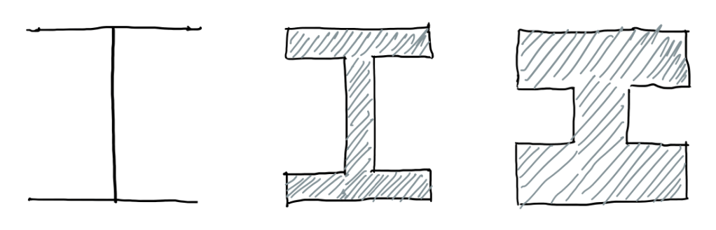
The case of an I-beam have some variants, as the ones with thick flanges and a short web, or thin flanges and long webs. Considering that, these bonds (Figure 1) have the same material and cross-section area, this last one is much more efficient in terms of sustaining the loads caused by bending and twisting. In terms of membrane loads, the one that not occurs in bending or twisting, it is less important to have a quite slender section. However, in terms of bending and twisting, it is very much important. The difference between the sandwich plate and general composite laminates, in terms of design aspects, is that the first is made by two skins and a honeycomb core.
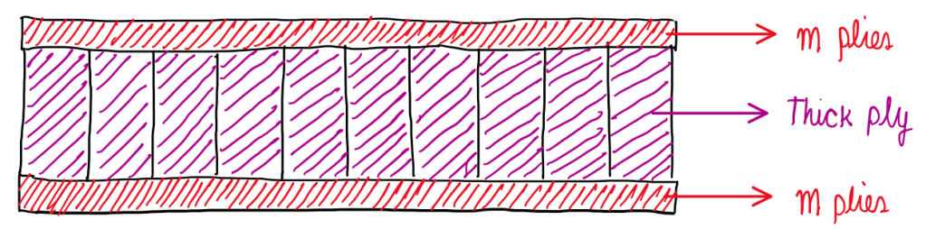
Figure 2 illustrates this case, where the 2 skins have m plies and these are separated by the honeycomb, that can be seen as a thick ply. The composite laminate, in the configuration seen in Figure 2, would have core as a thick ply. Hence, this includes the effects of the shear stresses, shear loads and the deformation under the shear stresses. The honeycomb, for instance, is rather deformable since is an empty structure even though it is metallic. A polymeric foam is another example of a very soft material. Some aspects of the classical lamination theory usually are not accounted for, so the out-of-plane shear deformation of the plies. Hence, the main difference between sandwich structures and composite materials, in terms of design procedures, is the comprehension of the effect of the core shear properties on deflection, buckling and stresses for the sandwich panel.
Modes of failure
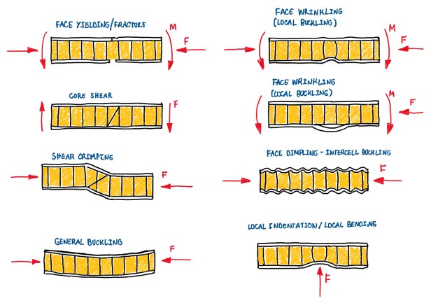
From the modes of failure, it is possible to understand what are the types of strength that should be kept under control. The basic modes of failure consider that, will occur some plastic deformation or they fade taking into account that sandwich plates are not always made by composite skins. These are not always made from carbon or glass fiber plies. However, in many applications it is used aluminum foils. In nautical construction and refrigerator cargos, for instance, are used aluminum skins. These may yield before failure (face yielding), in other words, they undergo some plastic deformation. This is not the case, normally, for composite skins. A second important mode of failure is the core shear. In this case, the core carries the shear loads, thus it would probably fail under shear with a crack that would be approximately oriented according to the principle stress direction. In the case of shear, this is about 45°. Another failure due to shear is caused by some misalignment on the structure. This generates a local buckling, the section is transformed into a shear failure of the core. This is also called shear crimping. There is also the possibility of the sandwich to suffer from the general buckling. In the most cases that general buckling occur, the panels are large, but they are not very thick. Hence, it is a case which a compression buckles the structure, that results on its elastic instability. Actually, there are other buckling modes of failures which usually are local, not global. These are the face wrinkling and face dimpling. The first means that, the material facing enters or detaches locally from the core, as can be seen on Figure 3. This may be a case which there is a weak bonding between the skin and the core, then under compression or bending, it is possible to have a local instability of the skin. The result is a kind of budging. In the face dimpling, the waviness or peach of the core is, in some cases, close to one of the modes of buckling of the skin. Actually, these are not close to the first mode of buckling of the skins, instead they are similar to a higher mode of buckling. This is the face dimpling. The local indentation is based in the occurrence of very concentrated load in a sandwich plate. The core will fail under compression, then it deforms in a permanent way, which characterizes the local indentation.
Design principles
These modes seem to be rather complicated, for an engineer it is better to pre-design a sandwich plate according to some of those failure mechanisms, then to check the occurrence of the other failure mechanisms. Actually, it is more important, for the pre-design, to taking into account that the facings will not failure under this kind of load. They must be sticky enough to withstand the design loads. The second important condition is that, the core shall be thick enough and have sufficient shear rigidity, so that the deflection will be in some way limited with respect to prescribed parameters. In addition, shear failure should not occur under the prescribed load, which is the core shear failure mode illustrated in Figure 3. In other words, the part is being designed against the failure of the core besides the possible limitations on deflection due to bending. Basically, the design is made against conditions face yielding and core shear failure modes, then the other conditions will be checked. The third basic design principle is to not have wrinkling and dimpling. Finally, it should be checked if the failure of the shear stress can be withstood by the bonding within the skins and the core.
Fundamental formulas
After verified the basic design principles, it is important to understand the fundamental formulas that describes sandwich components.
Bending stiffness of a sandwich beam (Equal skins)
Considering the deflection of a sandwich beam, it is important to have an understandable bending stiffness. This is something which is related, by definition of the beam theory, to the elastic modulus in the bending axis, the moment of inertia and the width of the section. Hence, if it is substituted the value of each of these components on the following formulas, it is possible to obtain the sum of the moment of inertia of the single component of the composite section.
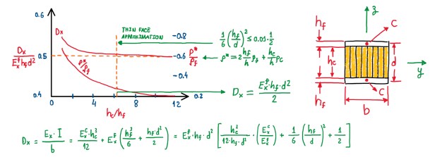
Ic = b•h3/12 ; I = A(d/2)2
The first formula is related to the core, the moment of inertia with respect to the Y-axis for the core. It is given by Ic, the moment of inertia of a rectangle section. Then, Ic is multiplied by the modulus of elasticity of the core, this is the bending stiffness of the core (Figure 4). The same is applied to the bending stiffness of the skins. The difference, in this case, is that the first term (Figure 4), the one that multiplies the modulus of the elasticity of the facings, times the height of the facing at the third power, is the bending stiffness along the axis which pass through the section of the skins. The second term is the transport moment of inertia.
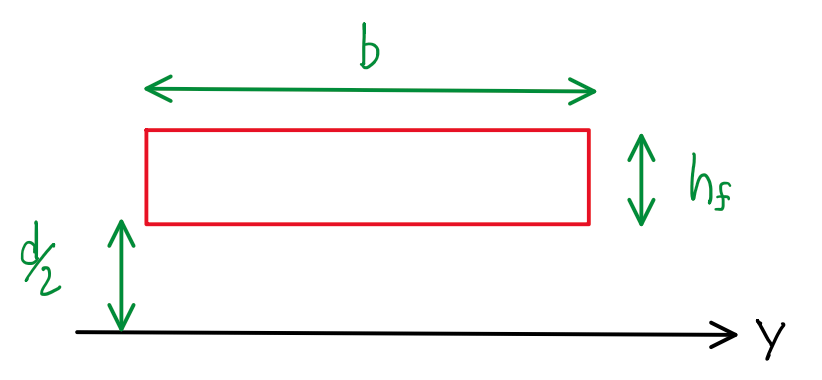
FIgure 5 illustrates a section b•hf which is located at a distance d/2, the distance between the center of the skins. The transport moment of inertia is given by:
I = (b•hf3/12) + b•hf(d/2)2
If there are two equal sections and these are located at the opposite directions with respect to the Y axis, the transport moment of inertia will be 2 times this equation. From Figure 4 and 5 it is possible to understand all the components of the bending stiffness. hf and hc refer to the height that comes from the facing and the ones that comes from the core, respectively. If the equation in Figure 4 is re-arranged in order to put in evidence the modulus of elasticity of the facings, the height of the facings and the square value of the distance, then the terms inside the brackets are more clear to be read. These are three, the ratio of the modulus of elasticity of the facings and the core, the rate of the height of the facings and the distance between them. The last term is a constant value 1/2. If this equation is plotted in a form that the Y-axis is Dx/(Exf•hf•d) and the x-axis is hc/hf, the first term is normally quite negligible. The reason is that, the Young’s modulus of the core is orders of magnitude lower than the one of the facings. For instance, for a polymeric foam, the Young’s modulus can be tenths of gigaPascals (GPa). The Young’s modulus of the facings is about three orders of magnitude higher than the polymeric foam. In terms of an aluminum honeycomb, despite the fact of this would lower, this kind of core has a very small quantity of material considering the volume that it occupies. Therefore, based on the rule of fixtures, also the Young’s modulus will be very low influent here.
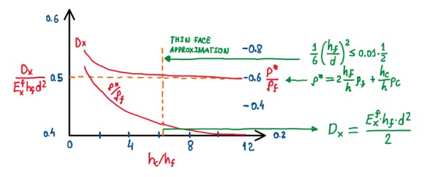
The difference might be done by the term (hf/d)2/6. If the equation plotted accounts this and the last term (1/2), then it is possible to get a point that the value of hf/d will be very low. Considering a situation which (hf/d)2/6 is just 1% of the third term (Figure 6). It is possible to admit, in engineering terms, that the first term is negligible with respect to the second term. Hence, if the height of the core is 5-6 times higher than the height of the facing, the laminate is in the limit of the thin face approximation. This means that, the bending stiffness is just related to the bending stiffness of the facings spaced apart each from a distance d (Figure 6). It is also possible to observe some correlation with the density (ρ* and ρf). The ratio of the density of the sandwich plate with respect to the density of the laminate (ρ*/ρf) also exhibits an asymptotic value, when plotted agains hc/hf. However, after the threshold of thin face approximation, ρ*/ρf tends to a constant value. Hence, it is better, as a general rule, to keep the value of hc/hf above 5-6. This value is not so high, actually. If the facings have couple of millimeters, it means that the height of the core will be about 10-12 mm, thus not a high value. The ratio ρ*/ρf is important, because the interest is that the skins withstand the bending loads and deformations, while the core just withstand the shear loads, which are related to bending. Otherwise, if the laminate is below the thin face approximation threshold, then the core also withstand some bending loads which is not desirable.
Bending stiffness for a sandwich beam with different skins
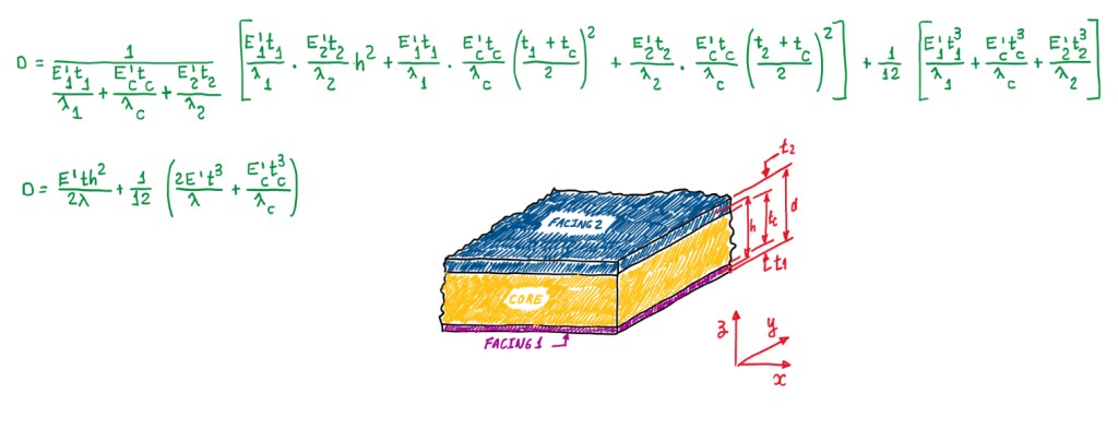
Figure 7 illustrates the bending stiffness equations for a sandwich plate with different facings. These exhibit different thickness and Young’s modulus. Actually, this configuration is not often used, but there are laminates with different materials for one side. This is usually applied for cases which the laminate is exposed to different environments at each facings. In the case of equal skins laminates, the formula applied is the one in Figure 4, that is adapted for the case in Figure 7. This last one has the inclusion of the term λ. This is equal to:
λ = 1 – νxy•νyx
λ = 1 – ν2 → Isotropic materials
The term λ for isotropic materials turns-out the denominator of the equation in Figure 7, because it is being considered a plate, thus a structure that deforms in two directions. Hence, the Poisson’s ratio should be accounted. In terms of sandwich plate cases, there are no significative differences on the formulas.
Stress in the face sheets and core of a sandwich beam (equal skins)
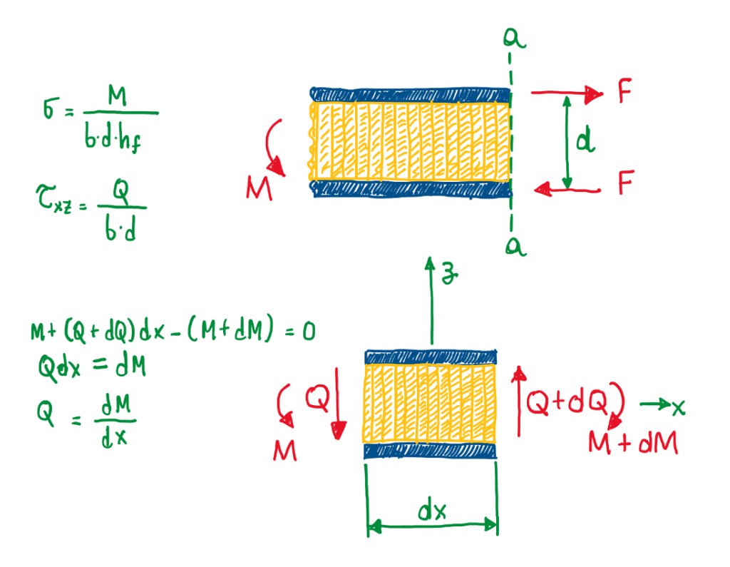
The stress for a sandwich beam with equal skins (Figure 8) has a basic approximation which is the thin skin/compliant core. This follows the design principles already investigated, which the main stresses are carried by the facings, while the shear stresses are carried by the core. An interesting way to understand this concept is considering an infinitesimal portion of the structure subjected to bending (Figure 8). As can be seen, there is bending moment at one side and at the other side it is possible to assume that this is supported by a couple of forces. These act in order to generate a tensile stress in the upper facing and compression in the lower one. These forces are spaced apart by a distance d, which is the distance between the center line of the skins. Therefore, the force which causes those stresses are simply M/d. Assuming that, the laminate is exposed to constant membrane stresses, the force is divided by section area (b•hf). Hence, the result is the stress (σ) seen at Figure 8. Actually, the constant membrane stresses is an approximation, since the bending moment will not give a constant stress distribution. In general, the stress distribution calculated in Figure 8 actually is an averaged value calculated across the section of the skins.
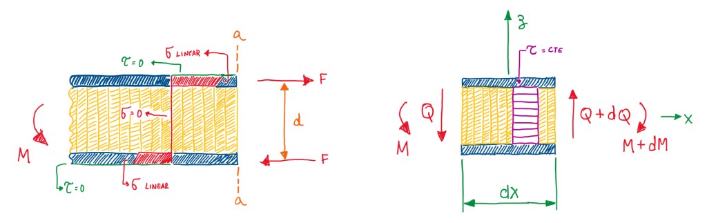
The stress distribution, in the case of bending in a section as the one seen in Figure 8, is represented in Figure 9. In the case of compliant core, which withstand only shear loads, the bending stresses are zero in the core and a linear distribution in the thickness of the skins. This is calculated in this way, because if the skin is very thin, the difference between the minimum and the maximum value is negligible. Hence, it is possible to simplify the problem of the stress calculation by just taking the average value. Due to the bending moment, there is a shear force described in Figure 9 by Q. This will be entirely supported by the core and the shear stress can be calculated by Q/(b•d), as seen in Figure 9. However, this is also an approximation, because the shear stress is constant in the core, thus this has a constant distribution inside the core. Another reason is that the skins have a negligible impact on the calculations, which is the thin skin approximation. Hence, by coherence, if σ is calculated using the approach seen in Figure 9, τ should be calculated by the same method (Figure 8 and 9). This was a demonstration that the shear loads are actually a derivative of the bending moments.
Stress in the face sheets and core of a sandwich plate
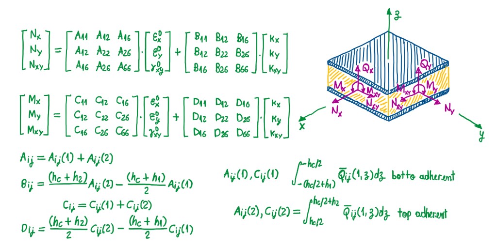
In the case of a plate with different skins, thickness and materials, there are not many ways to calculate the stresses. One of them is a sort of numerical analysis. Figure 10 illustrates a general formulation for n types of supports, plates and constraints, which are analytically available. If it is possible to calculate the moments or the forces that are acting on the plate, then it is possible to use the classical lamination theory (CLT) just neglecting the contribution of the core. This is given by the A, B, C and D matrices, also called ABDB matrices in some literatures, and given the relationship between loads, membrane deformations and curvatures of the plate. Alike the case of CLT applied to bulk laminates. This means that, it can be used the same types of calculation in order to calculate the terms of the ABCD matrix which was explicated in Figure 11.

When the terms have the number 1 between parenthesis, this means that they refer to the first skin, then the number 2 refers to the second skin. Hence, equations are referred just to the skin, no the core, because this one is neglected since it does not contribute to the terms of this matrix. In the case of symmetric skins, the B and C matrices become zero. Hence, the stresses on each ply of the skin can be calculated by the same approach for bulk composite laminates. In this case, the stresses in the core is just the value of the shear stress in the x or y directions divided by the height of the core. Then, it is not necessary to perform any other calculations for that.
Deflection of symmetrically loaded sandwich beam
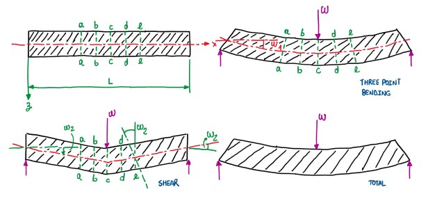
In sandwich beam cases, it should be put together two skins that are withstanding the bending and compliant cores. This last one withstand the shear loads. Hence, probably it is not being respected the basic rule, that states the neglection of the shear compliance. When performing calculations with the Timoshenko beam theory, compliance can be neglected. Hence, in this case, the deformations due to shear. This is not the case on the example of Figure 12. This is a sandwich beam subjected to a three point bending, that is based in two supports and a load in the middle. This situation exhibits a deformation due to bending, which is characterized by the displacement w1. Also in Figure 12, it is possible to see the deformation due to shear, mainly the shear of the core. This is characterized by the displacement and the angle of rotation w2 and w2′. Hence, these sections (Figure 12) rotate due to bending and due to shear and displace due to those loads. If this component is quite low, it can be calculated with mathematical means analyzed until now, but the shear deformations are not entirely known in terms of calculation procedure.
Deflection of a symmetrically loaded sandwich beam
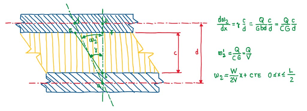
Figure 13 illustrates a section which is subjected to shear. W2‘ is the angle of rotation with respect to shear, while γ is the rotation of the section of the core only. The segment BC is the result of a rotation on the core that, initially was a segment BF. Hence, γ accounts only the rotation of the core. However, the total rotation is different from the rotation of the core. The reason is that there is the thickness of the two facings that, do not deform as the thickness of the core. It is possible to estimate the angle of rotation due to the shear W’, that is given by the derivative of W2′ along the axis of the beam (Figure 13). This is a proportion of γ and the ratio of c/d. This is based on the fact that, the distance from C and D is the same. Since this distance is the same, the angles are proportional to the distance between the points C and D. Hence, the angle γ can be calculated by just knowing the shear loads Q, the shear modulus of the core G and the section C. The shear stiffness of the core is given by V, which is equal to C•G. Hence, the angle W’ is equal to Q/V. This means that, since W2′ is also the derivative of the shear displacement, it is integrated to obtain the last equation seen in Figure 13. In the case of a beam with a load in the middle, W/2 is just the shear load. The integration constant normally depends on the boundary condition. However, in the case of a three point bending beam, the rotation is zero at the extremities, thus the constant of integration is zero.
∆2 = WL/(4V)
∆ = ∆1 + ∆2 = (WL3/48D) + (WL/4V)
w2 = (M/V) + cte
This means that, it is possible to calculate the maximum displacement due to the shear of the beam, which takes the value ∆2 at a distance of x = L/2. The total displacement accounts the terms due to bending, which depends on the bending stiffness of the beam, and the second term (Figure 14), which depends on the shear stiffness. This term, in the case of an isotropic or Timoschenko beams, is negligible, which is not the case for sandwich beams. It is possible to notice that, the term W•L/(4V) is the bending moment in the middle of the beam, which is the maximum value. Hence, the shear deflection is the bending moment divided by the shear stiffness plus a constant which depends on the shear stiffness.
Deflection of an unsymmetrically loaded sandwich beam
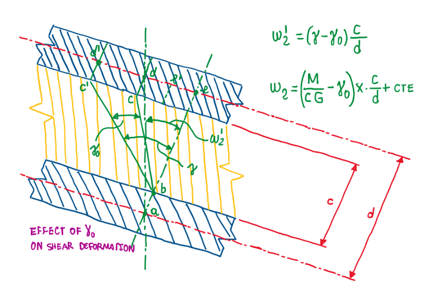
In the case of an unsymmetrical sandwich plate, the calculation of the shear deflection is a rather more complex. The rotation W2′ is calculated in the same process as previously, but there is an additional term γ0, that comes from the boundary conditions. This means that, in the load is displaced from the middle of the beam.
Other cases
There are some other cases with respect to sandwich plates. For instance, the deflection on simply supported, symmetrically loaded sandwich plates with isotropic skins and core, is the case which that the plate is supported all along the boundaries of the plate. The force or load is concentrated in the middle. There is also a similar case, but with a simply or partially support and symmetrical or unsymmetrical loads. In those case, the support is not distributed along the boundaries. The calculation for this case is normally done by numerical solution via Finite Element Method (FEM). In this case, the supports are just along the edges, which causes a deformation that, even in symmetrical loading, is unsymmetrical. However, the support along through edges are pretty enough for stability. Despite the fact that, the stresses can be estimated by the classical lamination theory, the deformations, specially the shear ones, are not straightforward to estimate.
References
- Carlsson, L.A. Kardomateas, G.A. Structural and failure mechanics of sandwich composites. Springer, 2011;
- MIL-HDBK-23-A, Structure Sandwich Composites. Department of Defence, DoD USA, 1974;
- DIAB Sandwich Handbook, DIAB AB, Sweden.
