The second part of the mechanical characterization deals with the compression and flexural tests. The first one is very similar to the tensile test in terms of procedures. However, the compression has different fixtures and specimens. The flexural test is based on a three point bending evaluation of the laminate. The specimen is simpler than tensile and compression tests. In addition, flexural tests complete the characterization since it provides the behavior under bending and the shear motivated by it.
Compression test – ASTM D6641
Determining the Compressive Properties of Polymer Matrix Composite Laminates Using a Combined Loading Compression (CLC) Test Fixture (ASTM D6641/D6641M-01). ASTM;
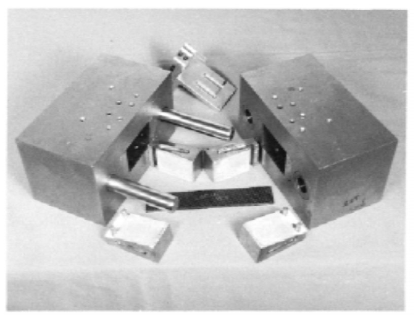
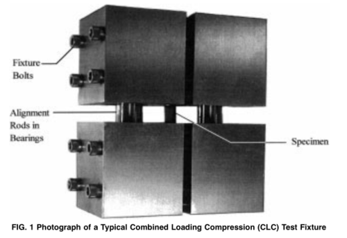
The compressive test based on the ASTM D6641 standard is known by its peculiar test fixture. This is called, combined loading compression test fixture, or CLC fixture. It is a bulky structure in which the specimen is fixed inside, but only a specified free length is left visible. The objective is to guarantee a proper loading of the specimen. In other words, this only suffers deformation due to buckling. For that, the alignment rods in bearing are fitted on CLC fixtures, which ensure that the specimen will only suffer compression. The main objective of the ASTM D6641 compression test is the definition of Young’s modulus. In this test, that parameter is different from the same for the tensile test. The difference between those moduli, in terms of magnitude, is that the compression is lower than the tensile modulus. However, this material is important in order to complete the material’s elastic behavior.
Determining the Compressive Properties of Polymer Matrix Composite Laminates Using a Combined Loading Compression (CLC) Test Fixture (ASTM D6641/D6641M-01). ASTM;
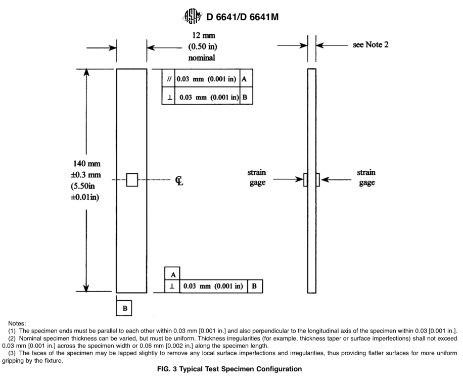
The specimen is a basic plate with a rectangular shape. It is 140 mm long, 12 mm wide and the thickness is defined per application. The main consideration regarding it is that its tolerance is about 0.03 mm across the specimen width and 0.06 mm across the length. This specimen is designed to be fitted to a strain-gauge or a proper sample in order to measure the strain. The test results are usually plotted in a stress-strain curve, which should exhibit a quite linear curve behavior until the plastic deformation. The linear part of the curve is used to measure the compressive Young’s modulus. This standard test is usually used to determine the ultimate compressive stress and strain at failure, the compressive modulus of elasticity and the Poisson’s ratio in compression.
Compression test – ASTM D3410
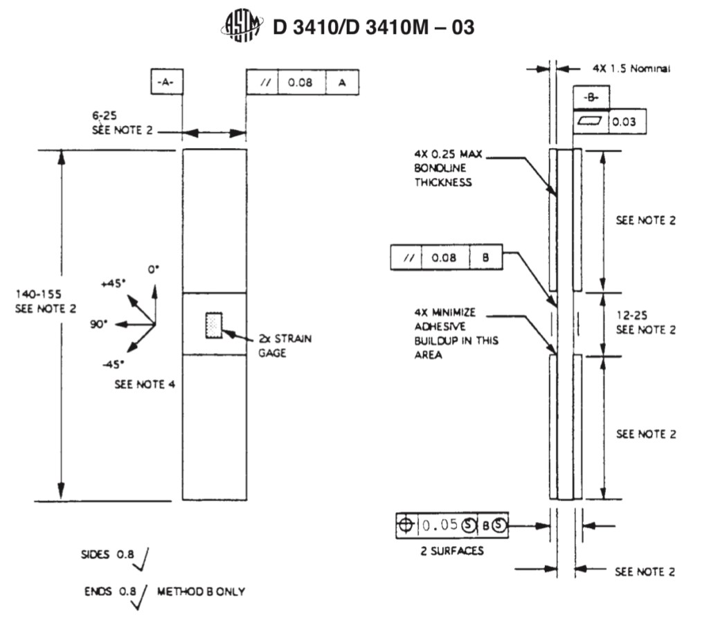
The compression test based on the ASTM D3410 has some distinctions with respect to D6641. The specimen is the main of these differences. It is a plate very similar to the specimen of the D6641 test, but it is usually fitted with tabs. These allow it to be fitted with strain-gauges that allow it to directly measure the Young’s modulus and the strain. However, this kind of instrumentation can be rather expensive since this test will be repeated 5-6 times with specimens from 5-6 different batches. Another important aspect with respect to the specimen, is that it is tested with different fiber orientations (0°, 45°, 90° and -45°). The gauge length is large, thus it has no local measurement. Actually, it is an extended length with respect to the D6641 specimen.
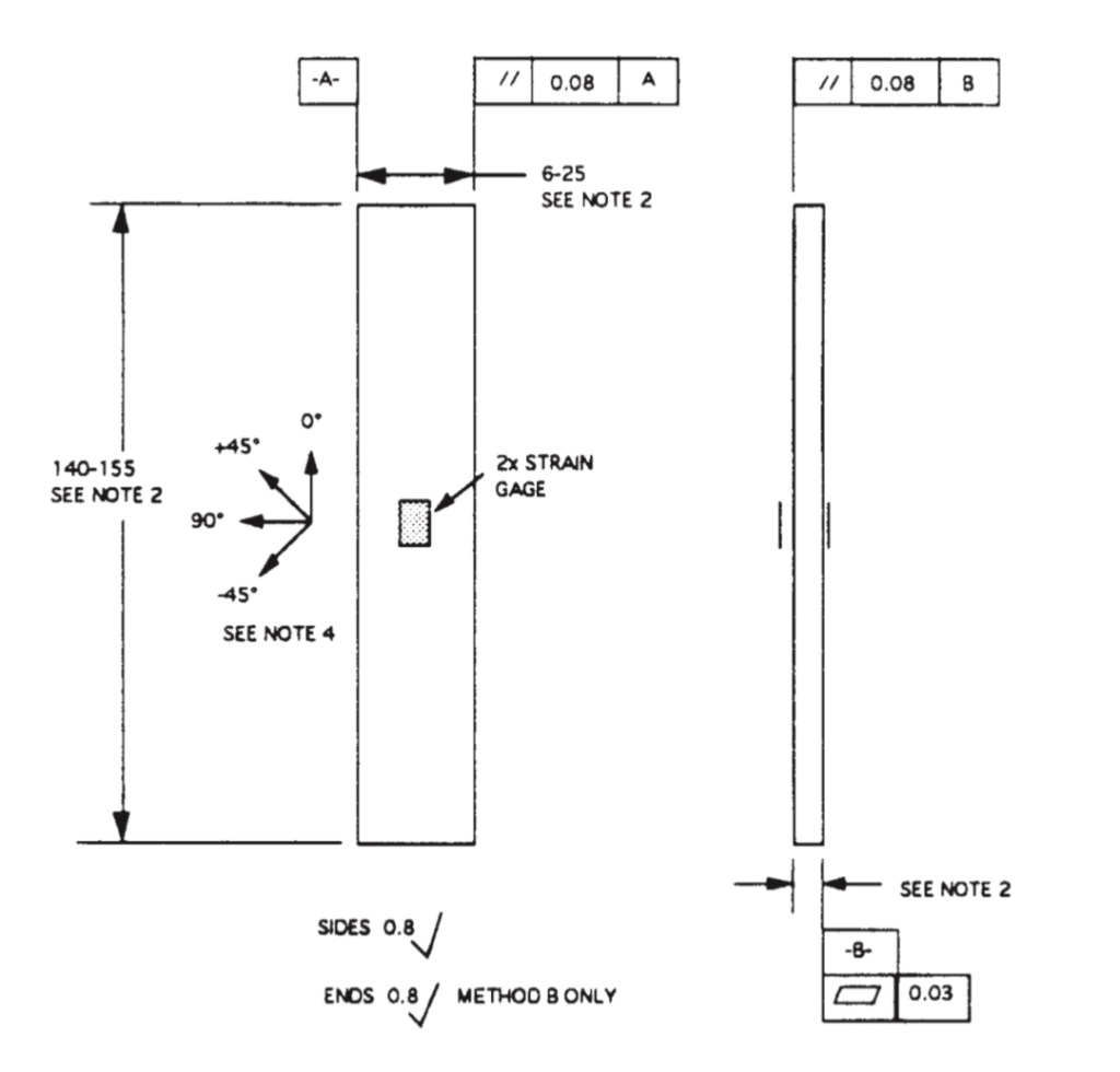
Regarding the sample geometry, this is similar to the one in the tensile test, which is defined by the D3039 standard. Hence, parameters as overall length, gauge length and fiber orientation are defined by the standards. This is quite important, because geometry and the stiffness considered for the specimen has a strong impact on the result.
Celanese arrange
When performing a compressive test in a composite material, there are other two important phenomena that affect it, the micro and macro stability. The last one is based on the stability due to the geometry. For instance, if a plate specimen is long and thin, when the compression test begins, this specimen will fail due to an out-of-plane deformation. This will be probably due to buckling, but it can also occur through bending, which is rather easier than that. A solution for this is that, the fixtures are fitted with edges in order to avoid any other kind of deformation.

The second phenomenon is micro-stability. As the name suggests, it is related to the micro-scale of the material. There are two different aspects that define the micro-stability, they are basically the laminate response when under pressure. The first aspect is that, the sufficient amount of fibers and their proximity. Actually, they are very close to each other. Hence, when the load is applied, the matrix is able to properly transfer the loads to the fibers. The second case is the opposite, there is low fiber volume, thus few fibers. When under compression loads, these tend to buckle due to the low interaction between them. In cases where the volume fraction is too low, the fibers inside are almost free to buckle. However, shear failure is possible to occur, because there is a different deformation between fibers and the matrix.
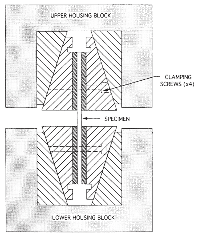
Hence, two compounds of the sample can behave in a different way. Usually, the shear failure occurs in the matrix, because it did not transfer the loads in an efficient way. In the case of high volume fraction, the failure of the specimen compounds tend to occur at the same direction of the applied load. Although the most usual design of the specimen is for high volume fraction, the fiber instability always occurs. The volume fraction is just one of the ways to avoid it. Actually, the specimens and components are properly designed considering the fiber instability. For this reason, the geometry is an important aspect, but more importantly, the use of anti-buckling structures to avoid this shear failure. This is the function of the celanese and CLC fixtures (Figure 5 and 6), for D3410 and D6641, respectively.
Curves
Similar to tension stress-strain curves, the same for compressive tests also exhibits a linear curve, but this is significantly smaller than the tensile one. The reason is the shear stress that also develops during the test. In addition, the transition from the compressive to shear is quite easy to observe in the curve. As a result, some procedures are necessary in order to account for those shear effects.
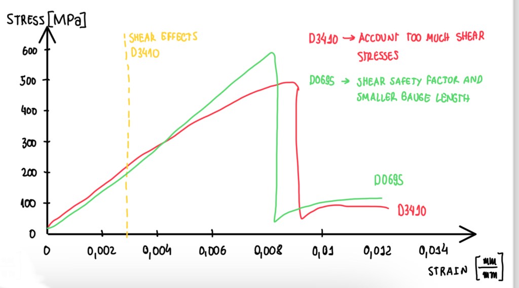
A modified version of the D3410 standard is proposed, this is the D0695 one. The objective is to introduce a shear safety factor in order to control the shear effect on the specimen. Then, it is possible to decouple shear from compression and determine in a more precise way the compression behavior of the component. The procedure done on the D0695 standard accounts for a smaller gauge length than the one for D3410 standards. In addition, not only safety factors on the stress-strain curves were adopted, but the shear considerations on the failure criteria.
Failure types
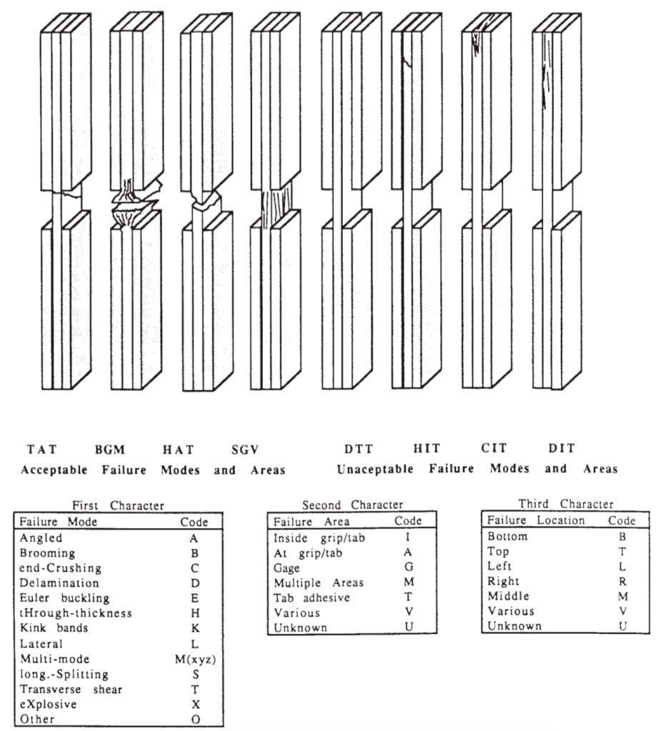
Similarly to the tensile test (D3039), the compressive test (D6641) also has some failures that are considered acceptable and non-acceptable. Usually, the NOK failures are caused at the tab and due to the delamination below it. Tabs can suffer from debonding, which indicates a bad preparation of the surface or improper bonding. The delamination can occur due to also a bond wrongly defined, which results in shear failure just below the tab. The problem of those failure modes is that they do not describe the material behavior. Actually, they are more connected to the adhesive characteristics. The acceptable failures are always related to the material. This only occurs at the free length region. Hence, it is possible to evaluate the compressive failure stress. However, if the specimen is not properly fixed, it will buckle. This also occurs on the free length, but it does not represent a compressive failure. Actually, it will be a shear failure due to buckle, but it is accepted. For this reason, it is important to use anti-buckling fixtures, because they reduce as much as possible the shear failure.
Compressive test – ASTM D695 and SRM 1R-94
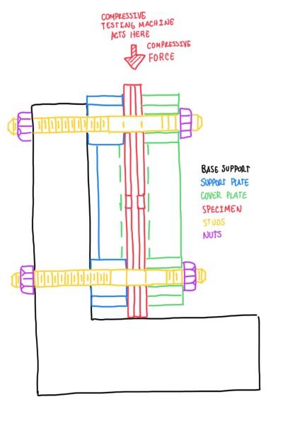
The ASTM D695 compressive test is very common in the motorsport field. In addition, the modified SRM 1R-94 standard is usually adopted for aircraft engineering, which is the reason why it is usually called Boeing Modified ASTM D695. This has more focus in the mechanical properties since in this field, safety is the top priority. Both standards vary with respect to D6641 and D3410 by the anti-buckling fixtures. Actually, they are used in this case, but there is also an external laminate that encapsulates the specimen. This avoids any misalignment improving the compressive loading on the sample (Figure 7). Another important difference between D695 and D3410 is the gauge length, which is less than 5 mm. This big difference reflects on the failure mode, from 5 to 20 mm gauge length, it is completely different. Combining a lower gauge length and an anti-buckling fixture, the shear failure is as much as possible avoided. Again, similarly to D3410, D695 and SRM-1R-94 also exhibit a linear behavior until failure, which is the plastic deformation of the sample. This occurs due to the micro-buckling. However, when comparing those standards, it is possible to notice that D695 and SRM 1R-94 exhibit a higher compressive stress at failure. This occurs mainly due to the reduction of the gauge length, which in D3410 occurs micro-buckling due to the higher value of that. This lets the specimen more exposed to shear loads, then the compressive stress at failure is reduced. Even though both tests deal with fibers of low modulus and stress at failure, in D695 seems to reduce as much as possible the shear stresses, these are not representative in high performance material.
Flexural test – D790
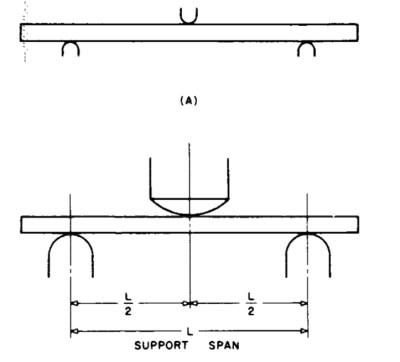
The flexural test is supported by the ASTM D790 standards. It is based on the three point bending arrangement. Hence, the material will be exposed to a compressive stresses at the upper part, while the bottom part is under tensile ones. The specimen might fail by compression. This occurs due to the micro-buckling at the upper layer of the specimen. The D790 flexural test is performed by the FEM department. These standards can be used to test several kinds of composites, from unreinforced to reinforced plastics. For unreinforced plastics or short fibers, it might be interesting that the specimen geometry is adapted to its conditions. In other words, a low modulus and more flexible material under bending. The reinforced plastics are usually high performance materials, but can also be unidirectional laminates or fabrics. In any case, the objective is to extract the elastic modulus for the compressive strength conditions.
Span length
The main parameters measured by this test are the Young’s modulus, the strain and the maximum stresses at failure. These depend on the effects of tension, compression and shear. This last one can be maximized or minimized by the span at which the specimen is exposed. Actually, this is a very important tune parameter for this test. The span length varies according to the type and the geometry of the specimen. A very or fully rigid sample requires a specific span. In some cases, there are basic span length to thickness ratios, which are 16/1 and 42/1. Usually, the thickness of the sample varies between 2 and 2.5 mm and the span length is about 96 mm. This is valid since the specimens are very similar to the one from the tensile test, thus a highly anisotropic material. Hence, the span length is defined according to the material, the thickness and the expected mechanical properties. Since the flexural test causes compression and tension at the upper and lower layers, respectively, the failure of the laminate will be due to one of these. This test can be performed for several materials, since the specimen is simple and easy to build. The main application of this test is for body work panels, because these car parts are usually being loaded by flection. As any other test, the flexural ones are performed at least 5-6 times, in order to generate stats. The main parameters as the elastic modulus, the strain and the maximum stress are registered at failure.
References
- American Society for Testing and Materials. (2001). Standard Test Method for
Determining the Compressive Properties of Polymer Matrix Composite Laminates Using a Combined Loading Compression (CLC) Test Fixture (ASTM D6641/D6641M-01). ASTM; - Suppliers of Advanced Composite Materials Association. (1994). SACMA Recommended Test Method for Compressive Properties of Oriented Fiber-Resin Composites (SACMA SRM 1R-94). SACMA;
- American Society for Testing and Materials. (2003). Standard Test Method for Compressive Properties of Polymer Matrix Composite Materials with Unsupported Gage Section by Shear Loading (ASTM D3410/D3410M-03). ASTM;
- American Society for Testing and Materials. (2002). Standard Test Method for Compressive Properties of Rigid Plastics (ASTM D695-02a). ASTM;
- American Society for Testing and Materials. (2003). Standard Test Methods for Flexural Properties of Unreinforced and Reinforced Plastics and Electrical Insulating Materials (ASTM D790-03). ASTM.
