The suspensions do not change the fundamental behavior of a vehicle, but they are capable to define how fast or slow the load transfers will occurs. Hence the vehicle dynamics is also related to the chassis itself, in other words, the structure which provides housing and support for suspensions, steering system and powertrain. As high the chassis stiffness, better will be the suspension operation, thus the vehicle dynamics and handling. This article will derive the equations related to the chassis stiffness and evaluate how much the car structure influences on the vehicle performance.
Effects of chassis torsional stiffness on lateral load transfer at the two axles
To understand the effects due to the lateral load transfer on the chassis, the following schematic is proposed:
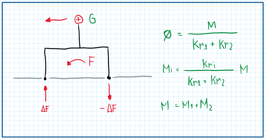
As can be seen, a centrifugal force acting on the point G, which represents the center of gravity, generates a moment M. Hence a load transfer from one side to the other occurs. In addition, a roll angle theta is produced. The terms Kr1 and Kr2 are the axle stiffness. M is partitioned between the two axles thus the amount of stiffness on these depends on their suspension parameters. Hence it is possible to verify the axle stiffness influence on the amount of load transfer and how the moment is partitioned. The main concern during the application of these equations is that they consider the chassis perfectly stiff. In general the anti-roll bars are used to allow a better control of the roll stiffness in one the axles or on both. In fact, it permits the control of Kr1 or Kr2.
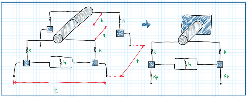
As this analysis is focused on one axle, it is possible to analyze only the half part of the chassis but with the twice of the rigidity. Hence considering the half portion fixed in a wall, it is possible to evaluate the chassis stiffness (Kt) and also the tyre stiffness (Kp).
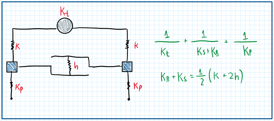
The main approach to evaluate the chassis stiffness is by setting extreme values for the anti-roll bar stiffness Kb. Hence there are two values for the chassis stiffness Kt, Krmax and Krmin:
It is possible to observe that this is an association of springs, thus the following equations can be developed:
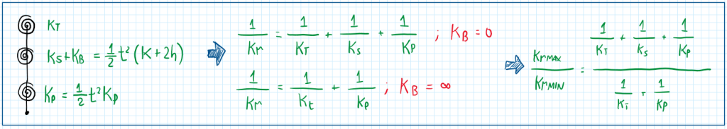
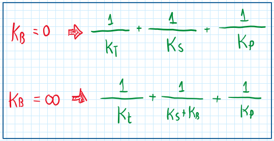
Hence Krmax / Krmin is the correlation between the extreme conditions of an anti-roll bar. It allows to evaluate the effects of the chassis stiffness Kt. Now the modifications will be applied on the Kt value inside the Krmax/Krmin ratio. Considering the Kt a very high value, in other words, infinite:
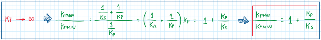
This relation is obtained for conditions of Kt tending to infinite and Kb = 0 or Kb tending to infinite. In fact this is a correlation of what happens when the chassis is extremely stiff, because in general the Kp (tire stiffness) is higher than Ks (suspension stiffness) alone. This means that Krmax / Krmin ratio has positive and large values. In terms of effectiveness of the chassis, a Kt tending to infinite increase the anti-roll bar effect. Therefore, as high the chassis stiffness is, more effective will be the anti-roll bars influence, which means more opportunity to tune vehicle dynamics. When Kt tends to 0, the Krmax / Krmin ratio tends to 1, which means that the anti-roll bars completely lost the effect. Therefore, the correlation developed above is a very important toll to evaluate anti-roll bar effectiveness. Hence, to be more easy to manipulate it is interesting to write it in the following form:
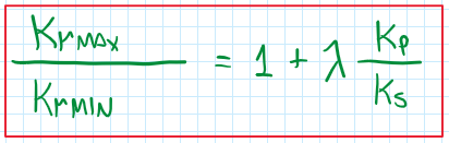
Therefore, this is the final form of the anti-roll bar effectiveness due to chassis stiffness. The parameter lambda is the chassis stiffness coefficient, which is defined experimentally. In general, lambda has bellow 1.
Chassis torsional stiffness and lateral load transfer
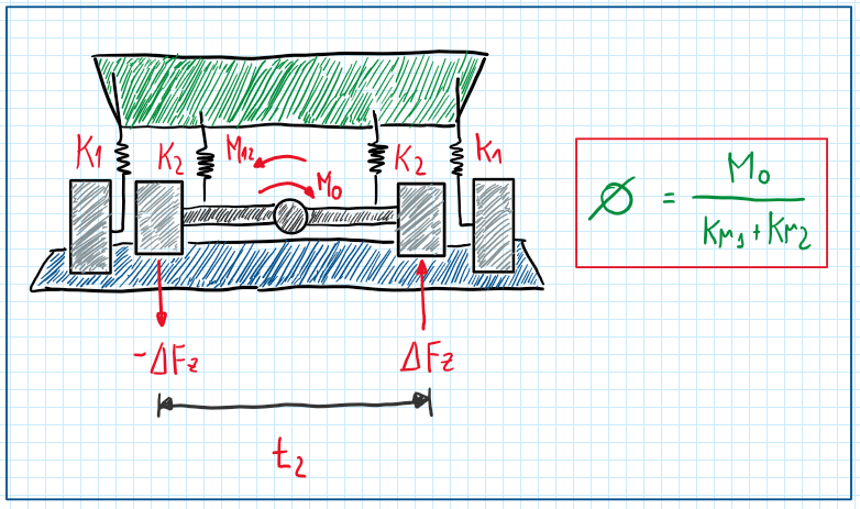
An usual situation for analysis is the lateral load transfer on rear wheel drive vehicles with live axle. This is also called resistant torque and its effects occurs under all vehicle operations. The differential transmits the torque provided by the transmission shaft to the wheels. As a reaction of the sprung mass a load transfer occurs. Hence it is possible calculate the roll angle due to this torque is the moment M0 is known. However, to better analysis it is useful to consider the torsional stiffness of the chassis as a rod supported by two torsional springs.
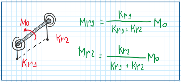
At this point, it possible to observe the effects on chassis due to the lateral load transfer motivated by the resistant torque. As a reaction, a moment M0 is generated on the chassis. Due to the assumptions that the chassis is reduced to a bar, the moment produced on each axle can be described by the formulas Mr1 and Mr2. Each of them is a reaction moment applied by the chassis on the axle. Hence, the Mr2 is a moment to the opposite direction of Mo and do not counter-balance it totally, because it is lower that. Therefore, to result in equilibrium condition:
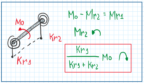
The last formula is the one of the additional moment applied by the chassis, through the suspensions, on the axles. In addition, this is the moment which results on the load transfer at the rear wheels. Hence, dividing the additional moment by the rear track t2:
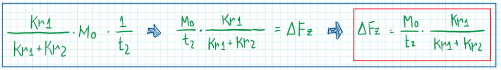
It is obtained the amount of load transfer to the most loaded rear wheel. However, considering now the less loaded rear wheel, it is possible to write the load on it. For this it is important to account the effects due to the longitudinal and lateral load transfer together.
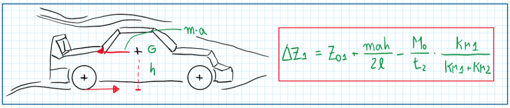
The equation deltaZ1 accounts all the loads on the rear axle, whose are the contributions of the static load, the longitudinal load transfer and the lateral load transfer. This last one is negative because the calculus was done on the less loaded rear wheel. These results are useful to calculate the traction limits on the critical rear wheel. The objective is to find values of load transfer which can limit the potential to accelerate.
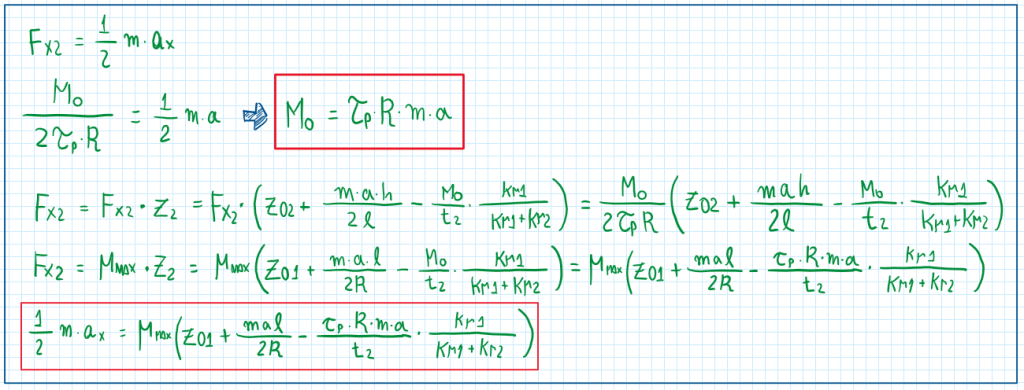
As can be seen, the maximum longitudinal acceleration is conditioned to the tyre characteristics (mu_max) and the effects of the lateral load transfer.
Anti-dive, anti-lift and anti-squat suspension mechanisms
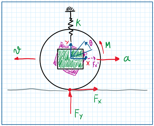
The automotive suspension must deal with three effects of the load transfer during vehicle operation, which are the lift, the dive and the squat. To avoid these suspensions are designed with mechanisms of anti-lift, anti-dive and anti-squat. The anti-dive is usually applied to the wheel hub, and has the following arrange. To analyze this situation it is considered a planar system which a wheel is under steady-state braking. Hence there is an acceleration a, which opposes to the velocity v direction. In addition, it assumed as reference, the center of the wheel hub. Hence it is possible to account the efforts due to the wheel hub translation and rotation (theta). As usual, the contact patch is exposed to two ground forces, Fx and Fy. However, in this analysis, Fy only accounts the longitudinal load transfer due to the braking. As the coordinate system is established at the center of the wheel hub, the Fx can be displaced from there. Hence a moment M must be added to compensate this change. To evaluate the compression suffered by the suspension during dive, the method of the virtual works is applied.
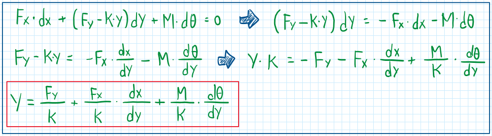
As can be seen there are two important derivative, dx/dy and d_theta/dy, these can be defined according to the assumptions made. For instance, d_theta/dy is usually assumed zero, thus the equation became:
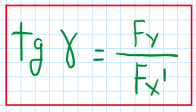
The first equation is well represented by the prismatic joint used in the hub design. With some manipulations of this equation it is possible to obtain a final relation between the ratio of forces and the the ratio of the derivatives. Hence the Y displacement is reduced in order to obtain the following relation:
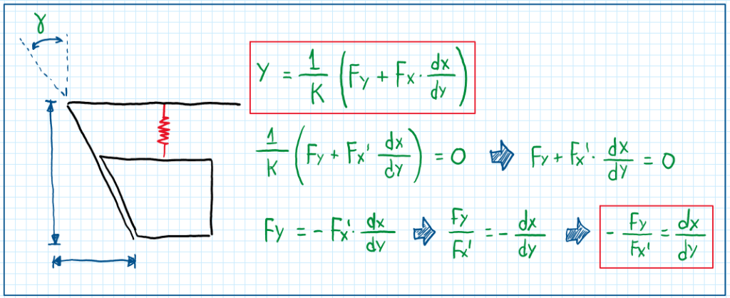
In addition making some assumptions, it is possible to model systems which deal with the dive effect without prismatic joints at the wheel hub. In this case the suspension arm is considered, thus assuming Y tending to 0 and dx/dy equal to 0:
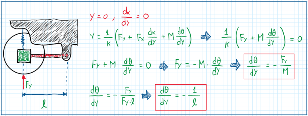
Finally, the moment generated will define the rotation of the hub. Hence, to avoid as much as possible the dive effect, the suspension arm must have a length according to the relation found in the end of the calculation. This means that the suspension arm length is defined according to the ratio of the angle relative to the vertical displacement which is set in order to obtain a desired wheel behavior.
References
- Guiggiani, Massimo. The Science of Vehicle Dynamics. Handling, Braking, and Ride of Road and Race Cars. New York, Springer, 2014;
- GILLESPIE, Thomas D, Fundamentals of Vehicle Dynamics, Warrendale, Society of Automotive Engineers, 1992. 470p.
