Race cars suspensions have the same function as the one for road cars. ensure that all wheels are in contact with the surface. The difference between them is the magnitude of the loads which they are submitted. In addition, the same components of these for racing application usually concentrate a lot of fucntions which results in complex shapes and high strength materials application. Basically, race cars suspensions are double wishbone ones with pull or push rods. This concept had appeared in early 60s and is still used today due to this main characteristic, provide total control of the wheel movement and its range. For road cars this concept has some problems with packaging, reason why it was substituted by McPherson or Multilink concepts.
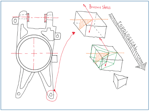
The upright is part of the unsprung mass of the vehicle, thus its characteristics are important for the vehicle dynamics. Over the years the upright was being optimized to complex shapes taking advantage of topological optimization. This one is a process which is made after the finite element analysis (FEA). However, before all these steps the work load of the vehicle must known to provide the correct information for these analysis. A vehicle upright is all based on wheel loads.
Obviously that in a race car most of the components requires a fine, precise and sometimes complex requirements. However, the upright design requires a deep knowledge about vehicle dynamics and machine design theory. The reason is the amount of requirements over just one part and these, sometimes, are antagonistic.
Upright functions
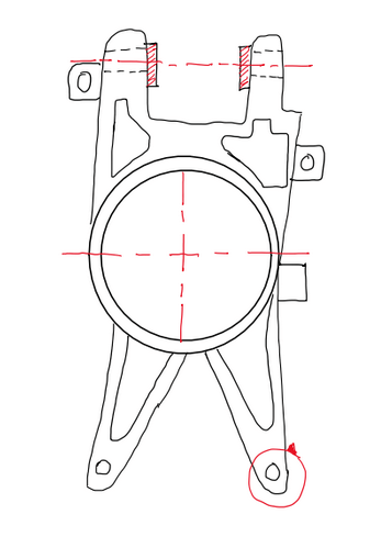
When any component are being designed, the first step of the designer is to question him or herself: “Which are the functions of this component ?” Usually, the second steop is a sketch drawing of the component made by hand. The main requirements and functions of the upright are summarized below:
- Connection of the wheel to the suspension arm;
- Housing and attachment for the safety tends;
- Contribute to the suspension kinematics;
- Support wheel loads;
- Define the pick-up points of the suspension components;
- Housing for brake calipers;
- Housing for the wheel hub and the components that supports it, as the wheel bearings;
- Provide a precise hole (bore) for the bearings.
To succed on these features, the designer should take advantage of the most advanced manufacturing techniques, materials, and design solutions, because uprights are components which concentrates a great amount of functions.
Upright features
As the upright concentrates many solutions, one of the features that it exhibits in its structure are precise holes. Actually, these are called bores, because this denomination refers to holes which were machined. In this case, there are several bores with the purpose of supporting components. The main problem with bores is that they concentrates stress. Hence, the upright designer must propose solutions to minimize the impact of bores. There are many solutions for this problem, which depend of the type of the upright and the design requirements. In general, the use of bushings are considered specially if the upright is a fabricated type one. The tapping is well-known and common procedure adopted. In addition, there are also bolt variations, because these also bring some issues.
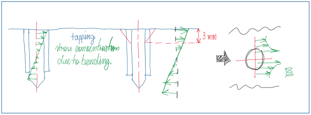
In general, the stress concentration of the bolt is due to the shear stress generated. Figure 2 illustrates that the highest stress occurs at the surface. Hence, the solution usually adopted is to choose bolts with a counter-sink head. As the stress is higher at the firsts threads of the bolt, the shear occurs at the top of the bolt and threads represents a stress concentration, the counter-sink help to provides a larger cross-section and also relief the stress. Another interesting feature of uprights is a small hole in the region of the wheel hub housing, more precisely, between the bearing. Hence, during operation, the hub rotates and traps some air in that region, which heats up together with the upright. The air expands, increases is volume and escapes easily by the hole. If there is no hole, the air is locked in that small volume and during its expasion, it pressure the bearing. The consequence is that the bearing grease are expelled by the air, thus bearings overheat and wear faster than usual.
Uprights also provides support for some components. The main ones are the wheel hub and its bearings. These are critical componentes, because they are correlated with important vehicle characteristics, for instance, fuel consumption, hub and bearing fatigue life. In fact, the housing for bearings must be carefully developed. Usually, race car uprights are largelly exposed to the high temperature from brakes, this will be transferred to the components at the vicinity. The upright is one of these. The expansion due to temperature occurs in three directions, thus it is easy for a bearing became loose. Hence, a precise fit tolerance is suggested for bearing asseblings, because at room temperature this one is assembled with a press, but at operation temperature it works without significative roling resistance. An incorrect tolerance results in bearing operation under longitudinal and transversal playing. The upright can also work as a support for brake ducts. These components are commonly used in top class race cars, as open wheels ones. Another important components are ABS and/or tire temperature sensors which are fixed at the upright. The main concern about this, is the amount of bores and their positions in the upright due to the stress concentration.
Upright technology
Since the upright is a such complex component, what defines the technology used for its manufacturing are its requirments, which are defined by vehicle design and vehicle dynamics department. Usually race cars follow strict rules that is focused in increase performance without lost of safety. Hence the regulations from a racing series defines the car layout, the wheel and rim size and the budget that each team is allowed to dedicate in technology and development. There are also other requirements as suspension kinematics, wheel bearings and brake specifications. These are usually defined by the vehicle dynamics department of the company which builds the car. In addition, components like bearings and brakes are carry over, thus the upright layout is usually adaptted to the dimensions of these components. The car builder and the part supplier usually decide together which is the best configuration according to the requirements. The last important point which defines the upright characteristics are the design targets. This also depends on the regulations rules, for instance, minimum weight. The design office defines parameters as weight-stiffness-strength and the aerobalance of the car. Since there are many requirements, it is common that the upright would request a high level of technology. The first technological feature of an upright is its material. In general, the main options are:
- Cast magnesium;
- Steel fabricated;
- CNC machined aluminum;
- Cast aluminum;
- Forged aluminum;
- Cast titanium (Investment casting).
Cast magnesium
The cast magnesium was largely used in the nineties due to its main advantage, its very low density, 1.8 g/cm^3 (Kg/dm^3). In addition, it is easily casted, despite the fact that requires some finishin after this process. However, it is not a strong material, it exhibits only 150-200 MPa of tensile strength and this results in a bad strength to weight ratio if compared to the aluminum. Cast magnesium parts also have problems in casting, because it develops pores during the process and there is no total control over this effect. This suggests that cast magnesium components can be very light, but its low strength make them critcal if these must be lightweight. The reason is the wall thickness obtained for lightweight parts which is very thin. This can expose the compoent to failure if it goes about 1.2 mm. Usually, former race car companies establish safety factors between 1.5 and 2.0 to avoid cracks during operation. In road vehicles cast magnesium uprights usually are made with a safety factor about 3. In any applications the definition of the safety factor also results on limiting the minimum thickness of the components. The main concern of the design engineer with cast magnesium uprights are the misuse loads, since a lightweight one is critical in terms of safety factor and cross-section thickness. The main cast magnesium used in the racing field is AZ91 and R25.
Steel fabricated
Despite its name, it is a kind of composite material. In fact, an upright made by fabricated steel not only combine several kinds of steel, as also different processes are performed during the manufacturing process. It uses sheets of steel combined with steel bushings and accessories as studs. The main advantage of this material is its simplicity. It is easy to develop a light and strong upright. In addition, the designer can take advantage of the high strength of the steel to use very thin metal sheets. However, this one can not be under 1.2 mm since these components are welded. Otherwise these parts will be distorted after welding process. Another problem with fabricated steel uprights are the cost, more precisely, the labor one. This material require a very skilled technicians to assembly bushings, studs and pivots. In addition, critical activities as welding and tapping are include in the sheet of operations. The problem with these activities is the consistency. It is very difficult to guarantee a fine tolerance since it depends of labor working. It is also possible to include the setup of tools and working conditions as relevant factors. Hence, the cost of an upright made from fabricated steel is similar to a CNC machined aluminum. The main steel grades used are the low carbon one (%C<0.03%), for instance, 4130 (30CD4 – %C<0.03%), 25CD4 (sheet metal, %C<0.025%), 18NCD5 (bushings, %C<0.018%), 15CDV6 (%C<0.015). The ultimate tensile strength of these materials vary between 800 to 1200 MPa.
Aluminum
The most used material for lightweight uprights are the aluminum. This has a very good strength to weigth ratio, because its density is about 2.8 kg/dm3 and its tensile strength variates between 200 and 500 MPa. This results in a better strength to weight ratio than cast magnesium. Although aluminum parts (cast or CNC machined) are not so light as cast magnesium, they are stronger. Hence, they combine a lightweight part with a high tensile strength. In addition, the casting or the CNC machining process of the aluminum is not so critical as the magnesium one. As a result, aluminum is better to work and less critical than cast magnesium.
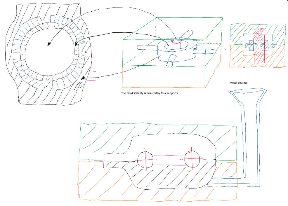
The main aluminum grade adopted in the racing field are the 2024 (Avional, with Cu), 2624 (alloyed with Cu) and 7075 (Ergal, alloyed with Zn). The aluminum is very well known material and its cost is more related to the manufacturing process used. Aluminum uprights are usually made by casting or CNC machining. The first is the most traditional manufacturing process in the industry history. The sand casting is based in two molds made by sand. This contain additive to increase the glue effect. The mold shape is made by a press with the negative form of the component. After that, a core, also made by sand, usually green sand, is placed inside the mold to create the internal shape and thickness of the component. The molds are tightly closed and the cast metal is poured inside the molds. Although the sand casting is very simple process, components made by this a finishing to reach the superficial quality. In addition the process usually results in shrinkage, which is the contraction of the material due to the heat transfer at very high rates. As a result, cast aluminum components require a more strict control of the process. In fact, this is not totally. For uprights, the core used requires some pins to lock this one in the right place during the casting process.
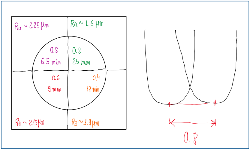
Another common process in the automotive field is the CNC machining with aluminum. In fact, this material fits very well with subtractive manufacturing due to its ductility. Nowadays the machining is made by CNC millings which are programmed with the component drawing and can work without interruption until the bach size is reached. CNC machined aluminum parts barely require finishing, usualy they are ready to be assembled. Despite the fact of the high cost of a CNC miling equipment, the process has a very low labor costs, which makes it more affordable than uprights made by steel fabricated and the process involved on it. Actually it is difficult to compare parts developed to be exclusively manufactured by CNC machining and the one made from steel fabricated. When developed only to be made by CNC, the shape of the components tend to be more complex, since this equipment allows this kind of construction. Hence, it is possible to develop shapes which requires less time and material. Another way to reduce costs in the CNC machining is the control of roughness. Figure 5 represents a surface with four different finishing made by a CNC. The objective is to compare the results and analyze the best approach for each situation. Ra indicates the roughness in micrometers µm. Eachs surface has two more number, one is the overlap of the spherical tool and the other the time required for the CNC machining to complete that job. With a CNC which is able to change its tool during the process, it is possible to give the proper finishing according to the finite element analysis FEA. In fact, evaluate which areas require a well and reasonable finishing demands a huge data about the system and the results from FEA.
There are another process performed when the upright is made from aluminum. These are post-processes and improve some characteristics of the component, the main ones are the anodizing, the shot peening and the rolling. The anodizing is performed in aluminum alloy components to improve its resistance to oxidation. Basically, it is created a layer of anodized aluminum by an electrolysis process. There are two types of anodizing, the hard and the decorative one. These are applied for different reasons, the first is to improve the material resistance to oxidation and also increase the superficial features of the material. Aluminum components submitted to the hard anodizing usually have improved their oxidation resistance, wear resistance and hardnes. There is also the possibility to apply silicon, PTFE or MoS2 to give a degree of lubrication in order to reduce wear rate. The decorative anodizing is usually applied to aluminum parts which the aesthetic factor has more relevance. It also improves the oxidation resistance, but without improvements in hardness and wear resistance. The anodizing is an affordable post process to improve the capability of CNC machining and cast aluminum processes. Actually, an aluminum component submitted to the anodizing process must have defined in its engineering, manufacturing and technical drawings its dimension before and after anodizing. However, this process must be applied carefully, because it usually reduces the fatigue, the thermal shock and alkali resistance of the component. In addition, it also is very difficult to be applied in high strength aluminum alloys.
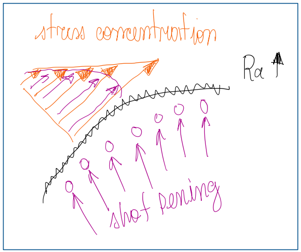
The shot peening is a process which small sphere of steel are shot against the component with the objective to cause a compression stress at the surface of the component. This provides a pre-stress on the material and increase the resistance to impacts. The plastic deformation on the surface also helps to increase the fatigue resistance of the component, because the pre-stress postpone the fatigue failure point.
Upright, wishbone and push-rod assembling strategies
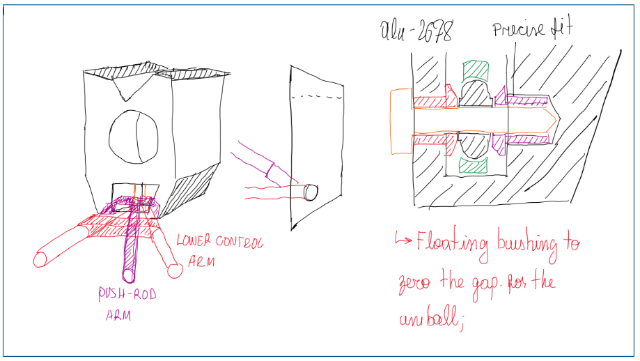
There are some strategies to connect the lower control arm to the upright, these are based on the use of bushings. These components have the function of provide means to connect bolts of high streght material in softer materials. For instance, high strength steel bolts and the aluminum upright. To reduce the stress on the main structure, a steel bushing is assembled between these two.
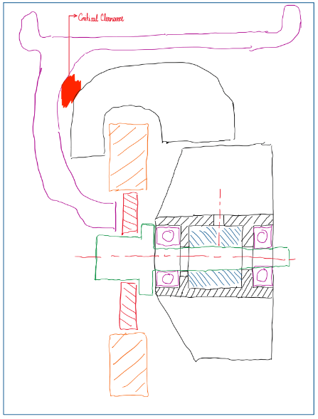
The float bushing (Figure 9) is a common approach which a gap is left on purposo between the bush and the uniball. The gap is zeroed when the bolt is fasten. During this process the bushing displaces and close the gap. The objective is to not provide a tight housing for the spherical joint, which reduces its performance and life cycle. The bushing used for this approach is called floating bush.
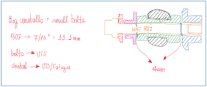
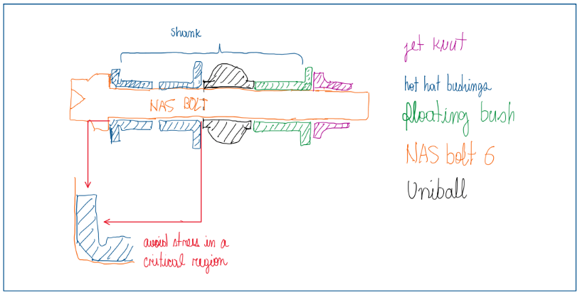
Another approach is the use of a big uniball with a small bolt. In this case, these components are made from a high ultimate tensile strength material, usually steel (HSS). Considering that the upright is usually made from aluminum, and this one has a good elongation, it is not so stiff as steel is. Hence, the assembling tends to transfer the stress to the upright. However, float bushings displace and close the clearence between the bushes. Bushings also have some technological features, for instance, the one which is contact with the bolt head, exhibits a chamfer and a stress neck. The chamfer is to avoid a direct contact with the most critical zone of the bolt head, while the neck is to avoid that an excessive torque applied to the bolt come to break this one. In these cases, the neck breaks and the bolt is preserved.
References
- Norton, Robert. Machinery Design, McGran Hill, 4th Edition;
- McKelvey S. A. Yung–Li L. Barkley, M. E. Stress-Based Uniaxial Fatigue Analysis Using Methods Described in FKM-Guideline. J. Fail. Anal. and Preven., 12, 445-484, 2012;
- SKF guidelines website;
- Pedersen, M. M. Introduction to Metal Fatigue. Aarhus University, 91, 2018, ISSN: 2245-4594.
