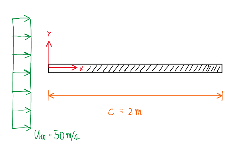
Considering an airflow which has a free stream velocity U∞ = 50 m/s and has an immersed flat plate exhibiting a stall condition. The reference system has x and y are parallel and vertical to the flat plate, respectively. In addition, the origin of the reference system coincide with the leading edge of the flat plate. There are two another coordinate frames, 1 and 2. The first establishes that x1 has a flow attached and with a velocity profile of:
u1(y’) = U∞[(y’ -1)³ + 1] ; y’ = y/δ(x)
Where δ(x) is the boundary layer thickness.
First part
The first part of this exercise has a the objective analyze some characteristics of the flat plate when at no slope condition.
Question 1 – Calculate the Reynolds number
Re = U∞∙x/ν = 50∙2/15∙10-6 = 6666666.667 = 6.667∙106 → Turbulent
Question 2 – Calculate the viscous stress at the wall in x1
u1(y’) = U∞[(y’ -1)³ + 1] = U∞[(y’² – 2y’ + 1)∙(y’ -1) + 1] = U∞[y’³ – 3y’² – 3y’]
u1(y’) = U∞[(y³/δ(x)³) – 3(y²/δ(x)²) + 3(y/δ(x))]
∂u1/∂y = U∞(3y²/δ(x)³ – 3∙2y/δ(x)² + 3/δ(x)) = U∞(3y²/δ(x)³ – 6y/δ(x)² + 3/δ(x))
τw = μ∙(∂u/∂y) = μ∙U∞(3y²/δ(x)³ – 6y/δ(x)² + 3/δ(x)) = 3μ∙U∞/δ(x)
δ(x) = 0.37∙x/Re1/5 = 0.37∙x/(U∞∙x/ν)1/5 = 0.37∙(x4/5∙ν1/5)/U∞1/5
τw = 3μ∙U∞/[0.37∙(x4/5∙ν1/5)/U∞1/5] = (3/0.37)∙μ∙(U∞6/x4∙ν)1/5 = (3∙18∙10-6/0.37)∙[506/(24∙15∙10-6)]
τw = 0.0845 Pa
As can be seen, the viscous stress is very small effect of the air flow over the flat plate when this is at zero degree slope.
Second part
The second part of this exercise deals with the second reference coordinate x2, which velocity profile is given by:
u2(y’) = U∞[2y’4 – 5y’³ + 3y’² + y’] ; y’ = y/δ(x)
Question 3 – Define what motivates the separation of the flow from the surface
The condition for flow separation is indicated by the velocity profile curvature, because for conditions at the wall, the velocity profile has the same sign of the pressure gradient. For the favorable pressure gradient, the curvature is negative throughout the surface and no separation occurs. Hence, to occur separation, the pressure gradient should be positive. At this condition, the curvature changes its sign and separation occurs for ∂u/∂y ≤ 0. Hence, the conditions for separation are ∂u/∂y ≤ 0 and ∂p/∂x > 0.
∂²u/∂y²|w ≈ (1/μ)(∂p/∂x) ; u2(y’) = U∞[2(y4/δ(x)4) – 5(y³/δ(x)³) + 3(y²/δ(x)²) + y/δ(x)]
∂u/∂y = U∞[2∙4(y³/δ(x)4) – 5∙3(y²/δ(x)³) + 3∙2(y/δ(x)²) + 1/δ(x)]
∂u/∂y = U∞[8(y³/δ(x)4) – 15(y²/δ(x)³) + 6(y/δ(x)²) + 1/δ(x)]
∂²u/∂y² = U∞[8∙3(y²/δ(x)4) – 15∙2(y/δ(x)³) + 6(1/δ(x)²)] = U∞[24y²/δ(x)4 – 30y/δ(x)³ + 6/δ(x)²] = 6U∞/δ(x)²
∂²u/∂y² = (1/μ)(∂p/∂x) = 6U∞/δ(x)²
∂p/∂x = 6U∞∙μ/δ(x)²
δ(x) = 0.37∙x/Re1/5 = 0.37∙2/(6.667∙106)1/5 = 0.0319 m
∂p/∂x = 6U∞∙μ/δ(x)² = 6∙50∙18∙10-6/(0.0319)² = 5.307 → Positive
∂u/∂y = U∞[8(y³/δ(x)4) – 15(y²/δ(x)³) + 6(y/δ(x)²) + 1/δ(x)] = U∞/δ(x)
∂u/∂y = U∞/δ(x) = 50/0.0319 = 1567.398 → Positive
Hence, the curvature is positive, which confirms that do not occur separation, but ∂p/∂x is also positive. This means that the pressure gradient adverse, but without separation. There are instabilities on the flow, but not enough to trigger separation.
Third part
The next part of the exercise proposes a third coordinate, which is x3 that has the following velocity profile:
u3(y’) = U∞[4y’4 – 11y’³ + 9y’² – y’] ; y’ = y/δ(x)
Question 5 – Calculate the viscous stress at the wall
u3(y’) = U∞[4y4/δ(x)4 – 11y³/δ(x)³ + 9y²/δ(x)² – y/δ(x)]
∂u/∂y = U∞[4∙4y³/δ(x)4 – 11∙3y²/δ(x)³ + 3∙2y/δ(x)² – 1/δ(x)]
∂u/∂y = U∞[16y³/δ(x)4 – 33y²/δ(x)³ + 18y/δ(x)² – 1/δ(x)]
τw = μ∙∂u/∂y = μ∙U∞[16y³/δ(x)4 – 33y²/δ(x)³ + 18y/δ(x)² – 1/δ(x)] = – μ∙U∞/δ(x) = – 18∙10-6∙50/δ(x)
τw = – 18∙10-6∙50/δ(x) = 0.0009/δ(x)
τw = – 18∙10-6∙50/0.0319 = 0.028 Pa
Question 6 – Calculate the lift
If the average CP at the front and at the base are given by CP,f = – 0.5 and CP,b = – 1.5, respectively using:
CP = (1/S)∫CP∙dS
and the flat plate assumes an inclination αS = 14°.
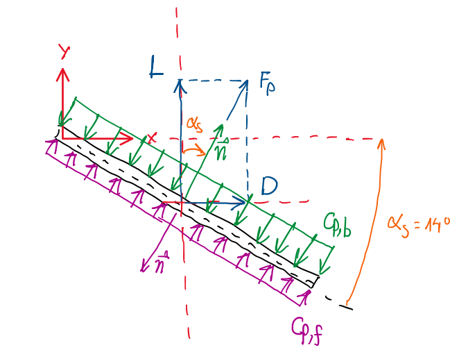
Lb = -q∞∫CP,b∙(n∙j)dS = -q∞∫CP,b∙(cosα)∙cdLZ = – q∞∙CP,b∙cos(α)∙c
Lf = -q∞∫CP,f∙(n∙j)dS = -q∞∫CP,f∙(-cosα)∙cdLZ = q∞∙CP,f∙cos(α)∙c
L = Lf + Lb = q∞∙CP,f∙cos(α)∙c + (- q∞∙CP,b∙cos(α)∙c) = q∞∙cos(α)∙c ∙ (CP,f – CP,b)
q∞ = ½∙ρ∙U∞² = ½∙1.2∙50² = 1500 Pa
L = q∞∙cos(α)∙c ∙ (CP,f – CP,b) = 1500∙cos(14°)∙2∙(-0.5 + 1.5) = 2910.887 N/m
Question 7 – Calculate the form drag
Db = -q∞∫CP,b∙(n∙i)dS = -q∞∫CP,b∙(sinα)∙cdLZ = – q∞∙CP,b∙sin(α)∙c
Df = -q∞∫CP,f∙(n∙i)dS = -q∞∫CP,f∙(-sinα)∙cdLZ = q∞∙CP,f∙sin(α)∙c
D = Df + Db = q∞∙CP,f∙sin(α)∙c – q∞∙CP,b∙sin(α)∙c = q∞∙cos(α)∙c ∙ (CP,f – CP,b)
D = 1500∙sin(14°)∙2∙(-0.5 + 1.5) = 725.766 N/m
Conclusion
Finally, it is possible to visualize that as soon the flat plate admits an angle, it is created a drag and lift components due to the pressure distribution over the surfaces. Hence, it is just to derive the pressure coefficient about the area by the following equations:
FP = -q∞∫CP∙n∙dS
D’ = -q∞∫CP∙(n)∙dS
L’ = -q∞∫CP∙(n∙j)∙dS
However, there are two faces of the flat plate, both are exposed to the pressure distribution, thus:
D’ = q∞∫CP,f∙sin(α)∙dS -q∞∫CP,b∙sin(α)∙dS
L’ = q∞∫CP,f∙cos(α)∙dS – q∞∫CP,b∙cos(α)∙dS
The sin(α) and cos(α) change due to the orientation of the n respective to the vector i and j, if it is pointing to the positive direction, the products n×i and n×j will be positive. Conversely, when n is at the opposite direction, the products n×i and n×j are negative.
